
Optical probe for cervical examination

Active Publication Date: 2021-01-14
BIOP MEDICAL
View PDF0 Cites 1 Cited by
  • Summary
  • Abstract
  • Description
  • Claims
  • Application Information

AI Technical Summary

Benefits of technology

The patent describes a method for creating a map that shows the likelihood of normal or abnormal tissue throughout the cervix. This is done by overlaying images of the cervix and measuring the likelihood of this tissue at different locations. This can help healthcare professionals better understand and locate abnormal tissue in the cervix.

Problems solved by technology

Second, these are slow growing tumors.
Unfortunately, the Pap test is unable to achieve a concurrently high sensitivity and high specificity due to both sampling and analysis errors.
Additionally, analyzing Pap tests is extremely labor intensive and requires highly trained professionals.
Colposcopic testing is a subjective exam and suffers from the following limitations:Non-standardized, variable procedureSubjective, unquantified ace to whitening observationsAccurate identification of optimal biopsy sites can be challengingMonitoring longitudinal changes is difficult
Biopsies may cause discomfort and bleeding to the patient, as well as anxiety.
In addition, experience does not appear to improve the performance of colposcopists (Bekkers et al.
Patient movement during examination can lead to inaccurate determination of the location of abnormal tissue, which can lead to inaccurate biopsy location and, therefore, false negatives during diagnosis.
None of the abovementioned prior art documents teach use of a colposcope.
Therefore, there is a long-felt need for an instrument that can differentiate between normal and abnormal tissues and provide a map of normal and of abnormal tissue areas in a scanned region, which does not require highly-skilled personnel to interpret the results, does not require a long interval between testing and diagnosis, and does not provide inaccurate results if a patient moves during testing.

Method used


Image

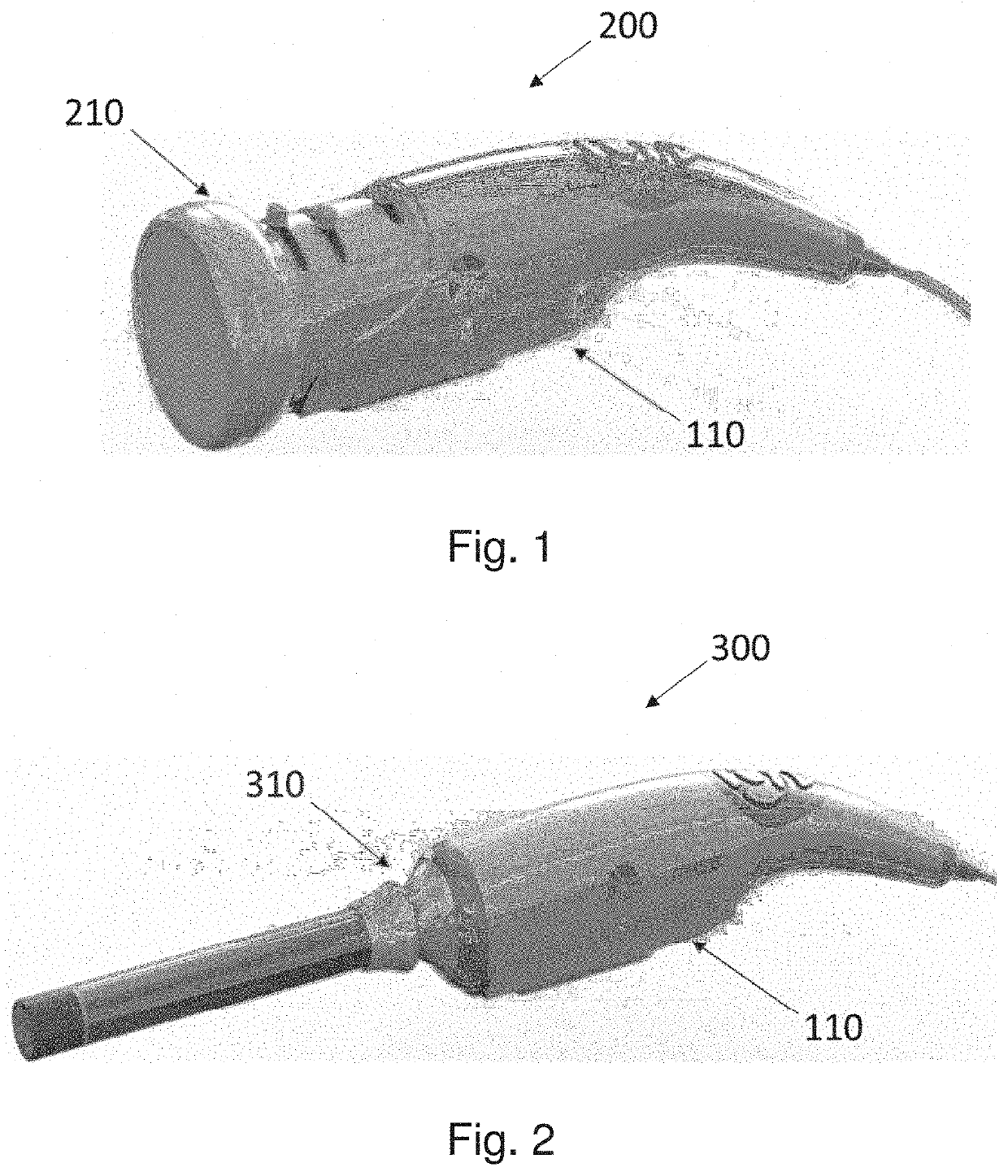
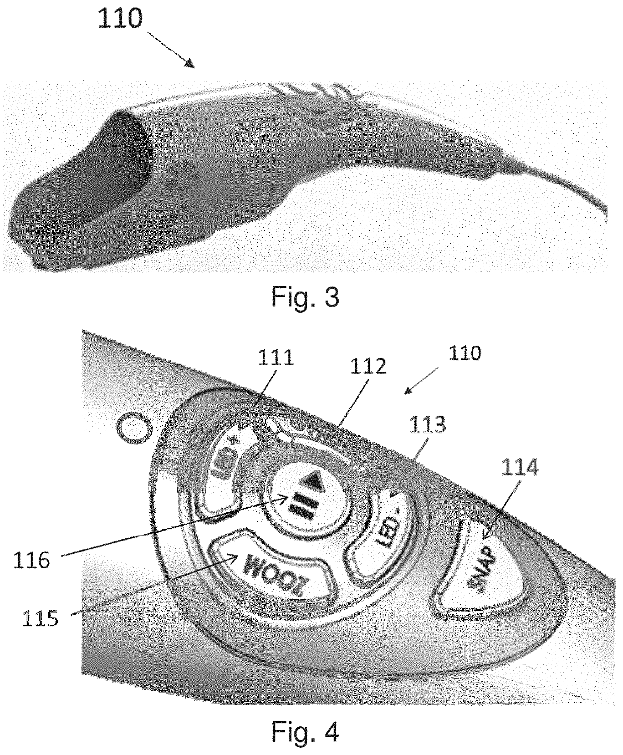
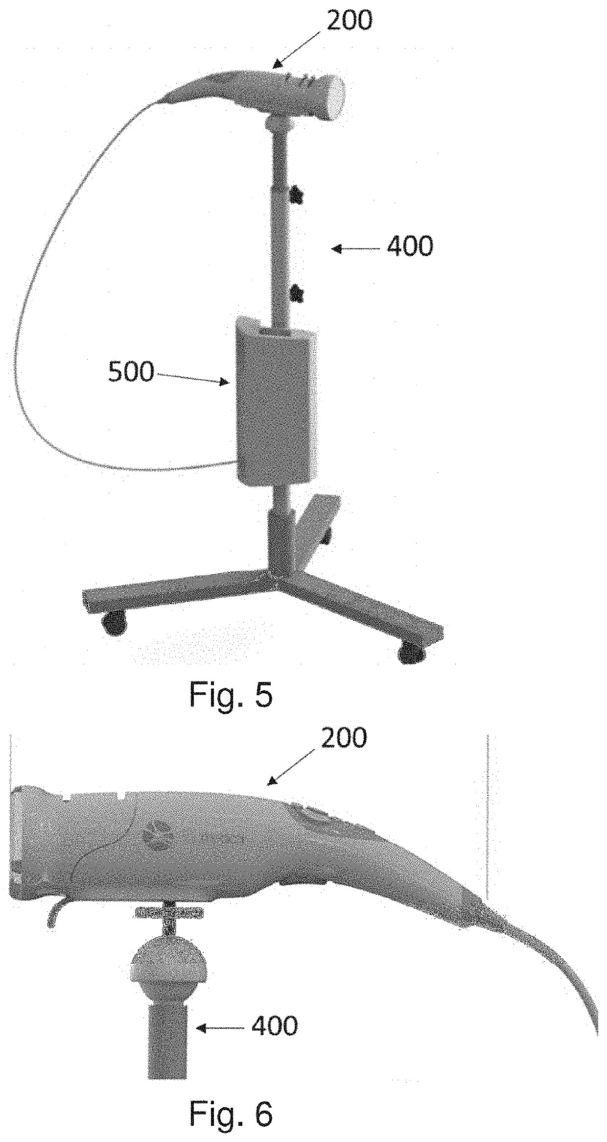
  • Optical probe for cervical examination
  • Optical probe for cervical examination
  • Optical probe for cervical examination

Examples


example 2

robe Laser

[0299]Wavelength—980 nm[0300]Beam divergence (α)—4.4 mrad)(0.25°)[0301]Optical Power—1 mW[0302]Continuous Wave[0303]Exposure time>10 s

[0304]The Optical probe laser is classified as a Class I laser because it meets the qualifications for a class I laser, where a class I laser is defined as:[0305]MPE retina (>10 sec): 4.1 mW[0306]MPE skin (>10 sec): 7236 W / m2

[0307]and the Optical Probe laser is:[0308]MPE retina: 1 mW[0309]MPE skin: 5100 W / m2

example 3

ht Source

[0310]In some embodiments the white light source is a fiber-coupled white light source including 4 dies.

example 4

olposcope

[0311]Illumination for the digital colposcope can be provided by a LED light source found on the body of the device which includes three white LEDs, each including 2 dies.


PUM


Abstract

A system for imaging and examination of a cervix, comprising a control module connectable with a changeable head configured to image the cervix and collect a tissue biopsy, the head selected from a group consisting of a digital colposcope module, a transvaginal optical probe module and an endo-cervical endoscope module. The system may additionally comprise light source(s) to illuminate cervix tissue; sensing device(s) to generate signal(s) from light and / or to acquire image(s) of a portion of a cervix; and processor(s) in communication with the sensing device(s). The system is configured to: (i) analyze the signal(s); (ii) detect the size of the cervix; (iii) determine parameters defining properties of the cervix; (iv) determine and distinguish normal tissue from abnormal tissue within the cervix; (v) determine the location of area(s) of abnormal tissue in the cervix; and (vi) generate a panoramic view of the cervix.

Description

FIELD OF THE INVENTION[0001]The present invention generally pertains to a system and method for providing an optical probe for cervical examination.BACKGROUND OF THE INVENTION[0002]Cervical cancer is one of the most common neoplasms of the female genital tract. It is the second-leading cause of cancer death among women in developing countries and the fourth cause of cancer-associated death worldwide. Early diagnosis of abnormal cells in the cervix prevents their development into cervical cancer and thus reduces morbidity and mortality.[0003]The uterine cervix is easily screened for several reasons. First, the tumoral changes occur in a specific area, called the transitional zone, around the “external os” (opening of the cervical canal into the vagina). Second, these are slow growing tumors. Third, this area is external to the body and can be easily observed by a gynecologist.[0004]One common screening method, the Pap test, has been in use for decades. During a Pap test, a large numb...

Claims


Application Information

Patent Timeline
IPC IPC(8): A61B1/303A61B1/06A61B1/04A61B1/00A61B1/07G06N20/00G16H30/20G16H30/40G16H50/30G16H40/63G16H50/20
CPCA61B1/303A61B5/0086A61B1/043A61B1/00105A61B1/00032A61B1/042A61B1/0638A61B1/07A61B1/00006A61B1/00142A61B1/00009A61B1/00045G06N20/00G16H30/20G16H30/40G16H50/30G16H40/63G16H50/20A61B1/063A61B1/00096A61B1/00172A61B1/00177A61B5/7267A61B5/0071A61B5/0075A61B5/0088A61B5/0091A61B5/05A61B5/1455A61B5/1459A61B5/4331A61B2218/008A61B2560/0233A61B5/004G16H50/70A61B1/000094
Inventor LANDESMAN, ILANKOSOBURD, TANIASEADIA, OZGORDON, SHIRI
Owner BIOP MEDICAL
Learn More