Ultrasound probe, control method of ultrasound probe, and ultrasound probe inspection system
a technology of ultrasound probe and control method, which is applied in the direction of ultrasonic/sonic/infrasonic diagnostics, instruments, applications, etc., can solve the problems of difficult to pull out a signal cable from the ultrasound probe and establish synchronization, and achieve excellent accuracy
- Summary
- Abstract
- Description
- Claims
- Application Information
AI Technical Summary
Benefits of technology
Problems solved by technology
Method used
Image

Examples
first embodiment
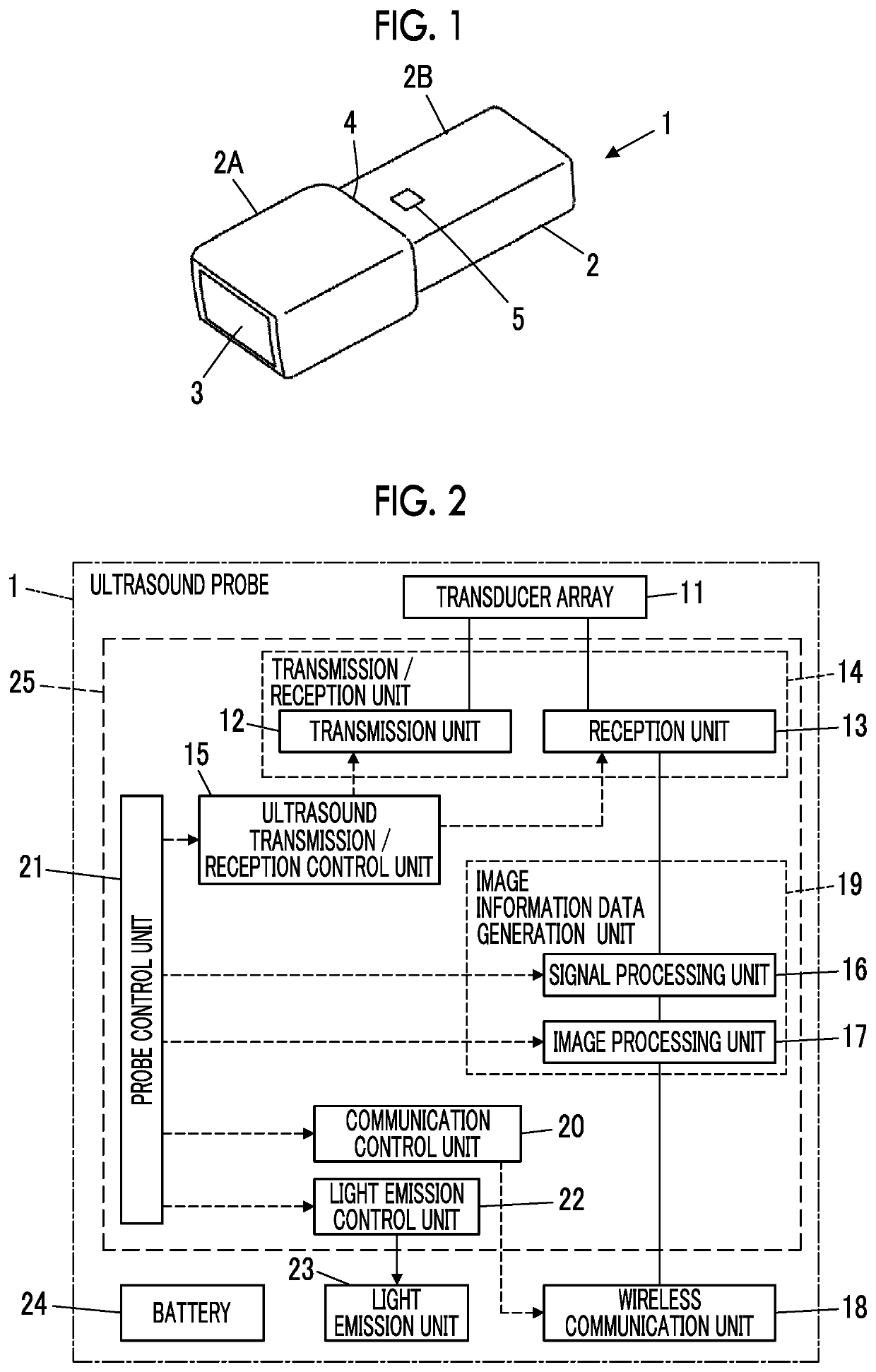
[0036]FIG. 1 illustrates an appearance of an ultrasound probe 1 according to a first embodiment of the invention. The ultrasound probe 1 has an almost rectangular prism-shaped housing 2, and an acoustic lens 3 is disposed on one end portion of the housing 2. The housing 2 is divided into a front portion 2A where the acoustic lens 3 is disposed, and a rear portion 2B on a side opposite to the acoustic lens 3, and a step portion 4 is formed between the front portion 2A and the rear portion 2B so as to surround the outer peripheral portion of the housing 2. Further, a light emission window 5 is formed in the vicinity of the step portion 4, on the rear portion 2B of the housing 2.
[0037]The housing 2 can be formed of various materials such as resin materials and metal materials.
[0038]FIG. 2 is a block diagram illustrating an internal configuration of the ultrasound probe 1.
[0039]The ultrasound probe 1 comprises a transducer array 11, and each of a transmission unit 12 and a reception uni...
second embodiment
[0095]FIG. 11 illustrates an internal configuration of an ultrasound probe 1A according to a second embodiment.
[0096]The ultrasound probe 1A is different from the ultrasound probe 1 of the first embodiment illustrated in FIG. 2 in that the ultrasound probe 1A further comprises a probe-side light receiving section 51 and a command acceptance unit 52 and uses a probe control unit 21A instead of the probe control unit 21. The probe-side light receiving section 51 is connected to the command acceptance unit 52, and the command acceptance unit 52 is connected to the probe control unit 21A. The ultrasound probe 1A has the same configuration as that of the ultrasound probe 1 of the first embodiment except for the probe-side light receiving section 51, the command acceptance unit 52, and the probe control unit 21A.
[0097]Further, the transmission unit 12, the reception unit 13, the ultrasound transmission / reception control unit 15, the signal processing unit 16, the image processing unit 17,...
third embodiment
[0101]FIG. 12 illustrates an internal configuration of an ultrasound probe 1B according to a third embodiment.
[0102]The ultrasound probe 1B is different from the ultrasound probe 1 of the first embodiment illustrated in FIG. 2 in that the ultrasound probe 1B further comprises a communication state detection unit 53 connected to the wireless communication unit 18 and uses a probe control unit 21B instead of the probe control unit 21. The communication state detection unit 53 is connected to the probe control unit 21B. The ultrasound probe 1B has the same configuration as that of the ultrasound probe 1 of the first embodiment except for the communication state detection unit 53 and the probe control unit 21B.
[0103]Further, the transmission unit 12, the reception unit 13, the ultrasound transmission / reception control unit 15, the signal processing unit 16, the image processing unit 17, the communication control unit 20, the probe control unit 21B, the light emission control unit 22, an...
PUM
 Abstract
Description
Claims
Application Information
 - R&D
- Intellectual Property
- Life Sciences
- Materials
- Tech Scout
- Unparalleled Data Quality
- Higher Quality Content
- 60% Fewer Hallucinations
Browse by: Latest US Patents, China's latest patents, Technical Efficacy Thesaurus, Application Domain, Technology Topic, Popular Technical Reports.
© 2025 PatSnap. All rights reserved.Legal|Privacy policy|Modern Slavery Act Transparency Statement|Sitemap|About US| Contact US: help@patsnap.com