
Peeling apparatus for aluminum plate material and method for peeling aluminum plate material

Pending Publication Date: 2021-01-14
FURUKAWA ELECTRIC CO LTD +1
View PDF3 Cites 0 Cited by
  • Summary
  • Abstract
  • Description
  • Claims
  • Application Information

AI Technical Summary

Benefits of technology

The present invention provides a peeling apparatus and method for peeling aluminum plate materials that are easy to use, environmentally friendly, and can be used in different settings. The apparatus uses a vibration along the stacking direction of the stack to generate a sufficient peeling force to separate the aluminum plate material from the stack, even if it is made thin or highly flattened, or if the outside diameter of the aluminum plate material changes. The method does not require immersion and drying of the aluminum plate material, simplifying the treatment steps and reducing environmental load. The apparatus configuration is simple, allowing for increased flexibility in implementation.

Problems solved by technology

Even if the aluminum plate materials are tried to be peeled one by one from the stack of the aluminum plate materials after the end of pressure annealing, the aluminum plate material cannot be easily peeled by a human hand.
However, in the art of Japanese Patent Application Publication No. 03-288742 described above, the aluminum plate materials are peeled via the liquid such as CFC-113 (Chlorofluorocarbon) as a medium for transmitting ultrasonic vibration, so that an immersion step, and a drying step or the like for the aluminum plate materials are required, and there arises the problem that the steps for peeling treatment are complicated.
Further, because waste liquid treatment for treating a used liquid is required, complicated treatment is involved, and an environmental load is also large.
Furthermore, it is necessary to install respective apparatuses for carrying out the immersion step and the drying step for the aluminum plate materials, so that the apparatus configuration is complicated, and an installation space is limited.
Further, all of the aluminum plate materials in a tank are peeled substantially simultaneously, so that there has been the fear that the aluminum plate materials contact one another in the tank and scars occur to the surfaces.
Further, in the art of Japanese Patent Application Publication No. 62-278254 described above, a pair of transducers each in a semi-arc-shape are disposed to sandwich the aluminum plate material from both sides thereof, and ultrasonic vibration is applied to the above described pair of transducers, so that when outside diameters of the aluminum plate materials are changed with change of specifications or the like, a pair of transducers have to be replaced at each time of the change, which is troublesome.
Further, the direction of the ultrasonic vibration is a direction parallel with the surface of the substrate, so that there has been the fear that the aluminum plate materials after peeled rub against each other and scratch the surfaces.
Further, since the entire wedge portions of the pair of transducers are inserted in the groove formed in the outer peripheral portion of the flattened aluminum plate material, the entire wedge portion needs to be formed on the substantially same plane, so that dimensional accuracy is required and the entire wedge portion cannot be inserted in the groove when a dimensional change occurs due to a secular change, and therefore it cannot be said that the aluminum plate materials can be sufficiently peeled.
Further, immersion and drying of the aluminum plate material is unrequired, so that the steps for peeling treatment are simplified, and the waste liquid treatment for treating a used liquid is also unrequired, so that troublesome treatment is not involved, and an environmental load is extremely small.

Method used


Image

  • Peeling apparatus for aluminum plate material and method for peeling aluminum plate material
  • Peeling apparatus for aluminum plate material and method for peeling aluminum plate material
  • Peeling apparatus for aluminum plate material and method for peeling aluminum plate material

Examples


Embodiment Construction

[0031]Hereinafter, embodiments of the present disclosure will be described while referring to the drawings.

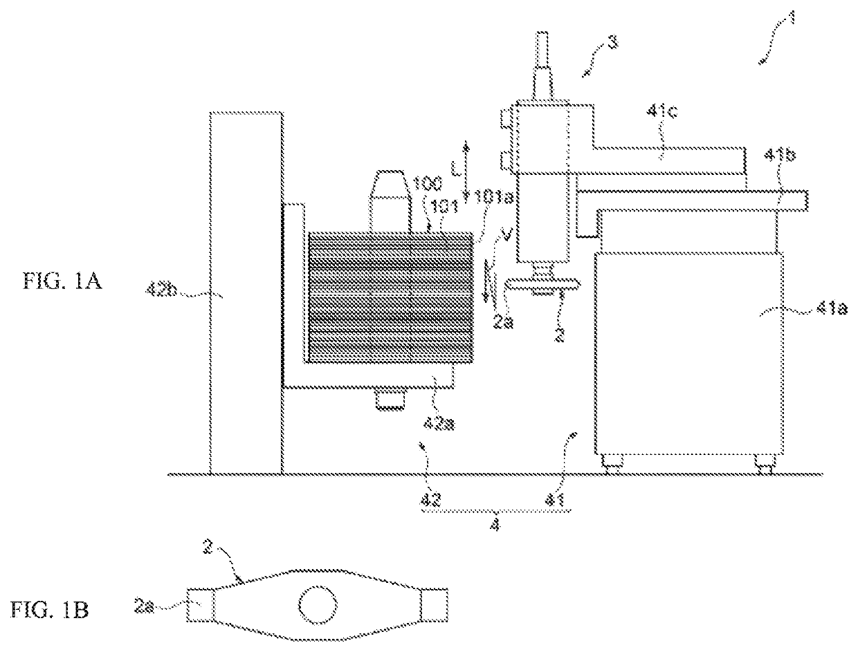
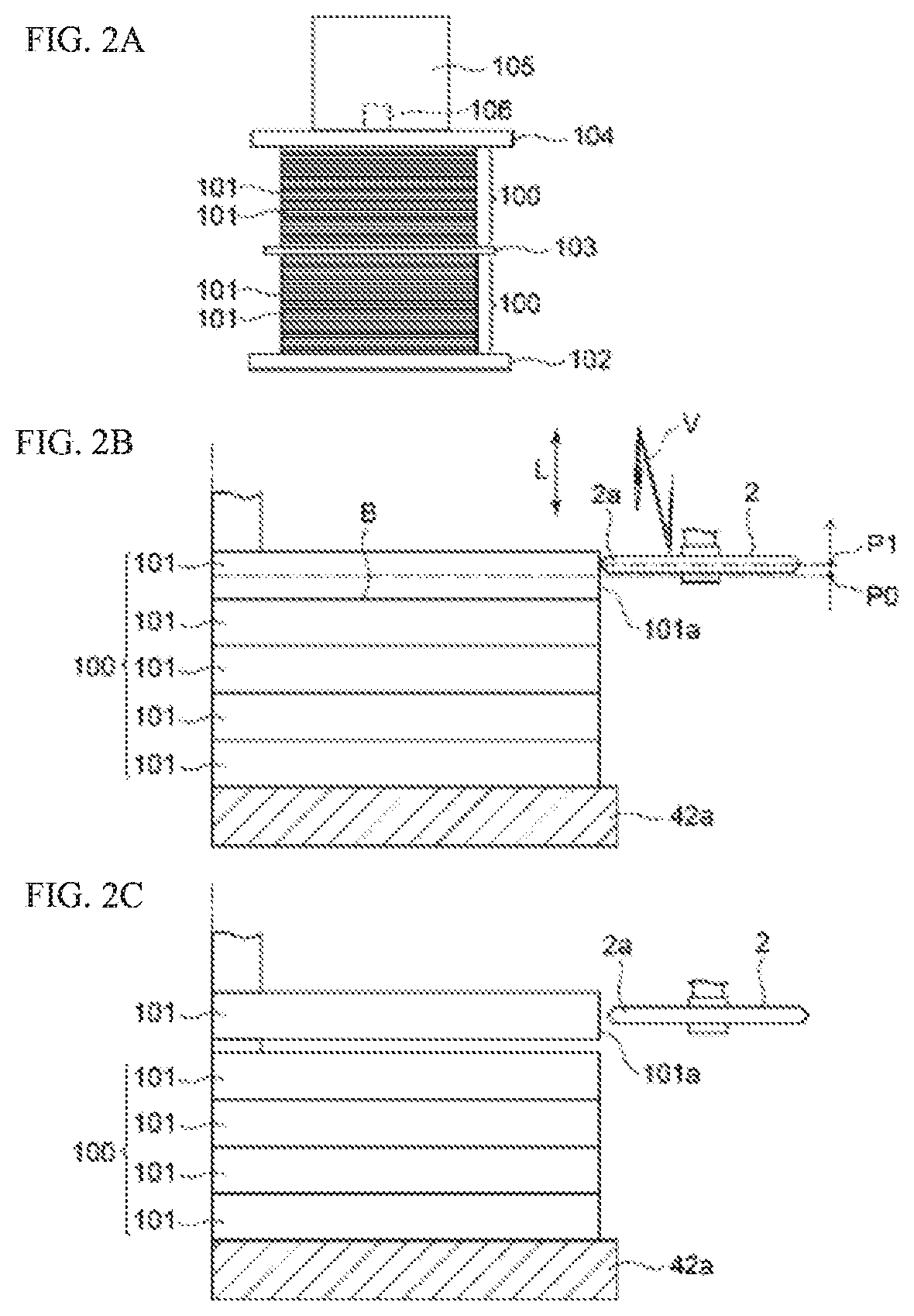
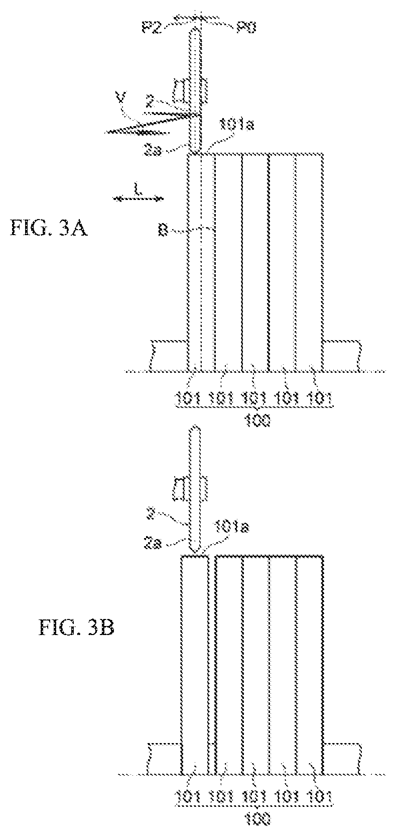
[0032]FIGS. 1A and 1B illustrate a configuration of a peeling apparatus for an aluminum plate material according to the present embodiment, FIG. 1A illustrates an entire view of the peeling apparatus for an aluminum plate material, and FIG. 1B illustrates a plan view of a vibration transmitting section 2 described later. Note that FIGS. 1A and 1B illustrate one example of the configuration of the peeling apparatus for an aluminum plate material, and a configuration of the peeling apparatus for an aluminum plate material of the present disclosure is not limited to the configuration illustrated in FIGS. 1A and 1B.

[0033]As illustrated in FIGS. 1A and 1B, a peeling apparatus 1 for an aluminum plate material is configured to be able to peel one or a plurality of aluminum plate materials from a stack 100 of aluminum plate materials in which a plurality of aluminum plate materials 101...


PUM

PropertyMeasurementUnit
Thicknessaaaaaaaaaa

Abstract

A peeling apparatus for an aluminum plate material is configured to be able to peel one or a plurality of aluminum plate materials from a stack of aluminum plate materials in which a plurality of aluminum plate materials are pressure-annealed and adhered to each other. The peeling apparatus includes a vibration transmitting section that is configured to be able to abut an outer peripheral surface of an aluminum plate material and is configured to be able to apply vibration along a stacking direction of the stack to the aluminum plate material, and a transducer that generates the vibration, and transmits the vibration to the vibration transmitting section.

Description

CROSS REFERENCE TO RELATED APPLICATIONS[0001]The present application is a continuation application of International Patent Application No. PCT / JP20191013087 filed on Mar. 27, 2019, which claims priority to Japanese Patent Application No. 2018-069344, filed on Mar. 30, 2018. The contents of these applications are incorporated herein by reference in their entirety.BACKGROUNDTechnical Field[0002]The present disclosure relates to a peeling apparatus and a peeling method for an aluminum plate material that peel each aluminum plate material from a stack of aluminum plate materials in which a plurality of stacked aluminum plate materials are pressure-annealed and adhered to each other.Description of the Related Art[0003]For example, for an aluminum plate material such as an aluminum substrate for magnetic disk, correction of flatness is performed by pressure annealing in order to secure flatness thereof. Correction treatment of flatness is performed in a state where a plurality of aluminum...

Claims


Application Information

Patent Timeline
IPC IPC(8): B32B43/00B32B15/01B65H1/04B65H3/62
CPCB32B43/006B32B15/016B32B2457/00B65H3/62B65H1/04B65H41/00B65H2515/50B65H5/008B65H2301/42342B65H2301/441B65H2701/1732Y02P10/20
Inventor NAKAMURA, TOSHIHIROTAKAHASHI, HIDEKIIMAKAWA, KIMIEKITAMURA, NAOKIKITAWAKI, KOTAROMURATA, TAKUYA
Owner FURUKAWA ELECTRIC CO LTD
Learn More