
Breakable locking cap for a container comprising a neck

a locking cap and container technology, applied in the field of locking caps, can solve the problems of difficult to pull on the inner ring in a repeatable manner, lack of repeatability of the opening between the two devices, and inability to completely remove the device in order to extract the stopper

Active Publication Date: 2021-01-14
A RAYMOND & CO
View PDF0 Cites 4 Cited by
  • Summary
  • Abstract
  • Description
  • Claims
  • Application Information

AI Technical Summary

Benefits of technology

The present disclosure proposes a locking cap for a container that can reliably seal the closure and be easily and repeatedly removed for accessing the container's contents. The cap includes a cage with a breakable part and a plurality of flexible tabs that block the stopper or bear under the container's collar in its locked position. The cage has a breakable zone located near the opening tab, which can be caused to break by applying a tensile force to the opening tab. The use of the locking cap allows for ergonomic and secure removal of the cap. The container also includes a neck with a circular opening and a stopper connected to the locking cap. The cap can be easily transitioned from an intermediate holding position to the locked position on the container when a force of between 30 N and 70 N is applied to the cap.

Problems solved by technology

A drawback of this solution comes from the lack of repeatability of the opening between two devices, in particular from breaking the breakable deformable bridge, since it is difficult to pull on the inner ring in a repeatable manner until the bridge breaks.
Another drawback of this solution comes from the lack of repeatability of the assembly between the inner and outer rings, which assembly must seal the closure.
EP2464577 sets out a device for locking a stopper in the neck of a reliable and repeatable container in terms of sealing the closure, but does not allow the device to be completely removed in order to extract the stopper.

Method used


Image

  • Breakable locking cap for a container comprising a neck
  • Breakable locking cap for a container comprising a neck
  • Breakable locking cap for a container comprising a neck

Examples


Embodiment Construction

[0035]In the descriptive part, the same reference signs in the drawings can be used for elements of the same type. The drawings are schematic representations that, for the sake of readability, are not necessarily to scale.

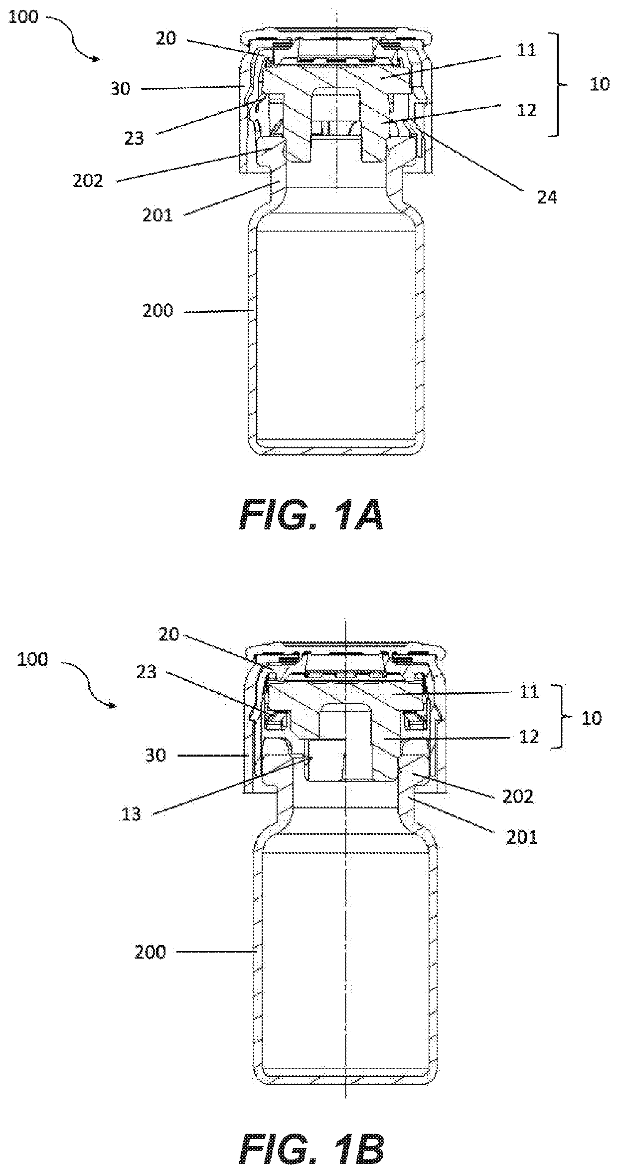
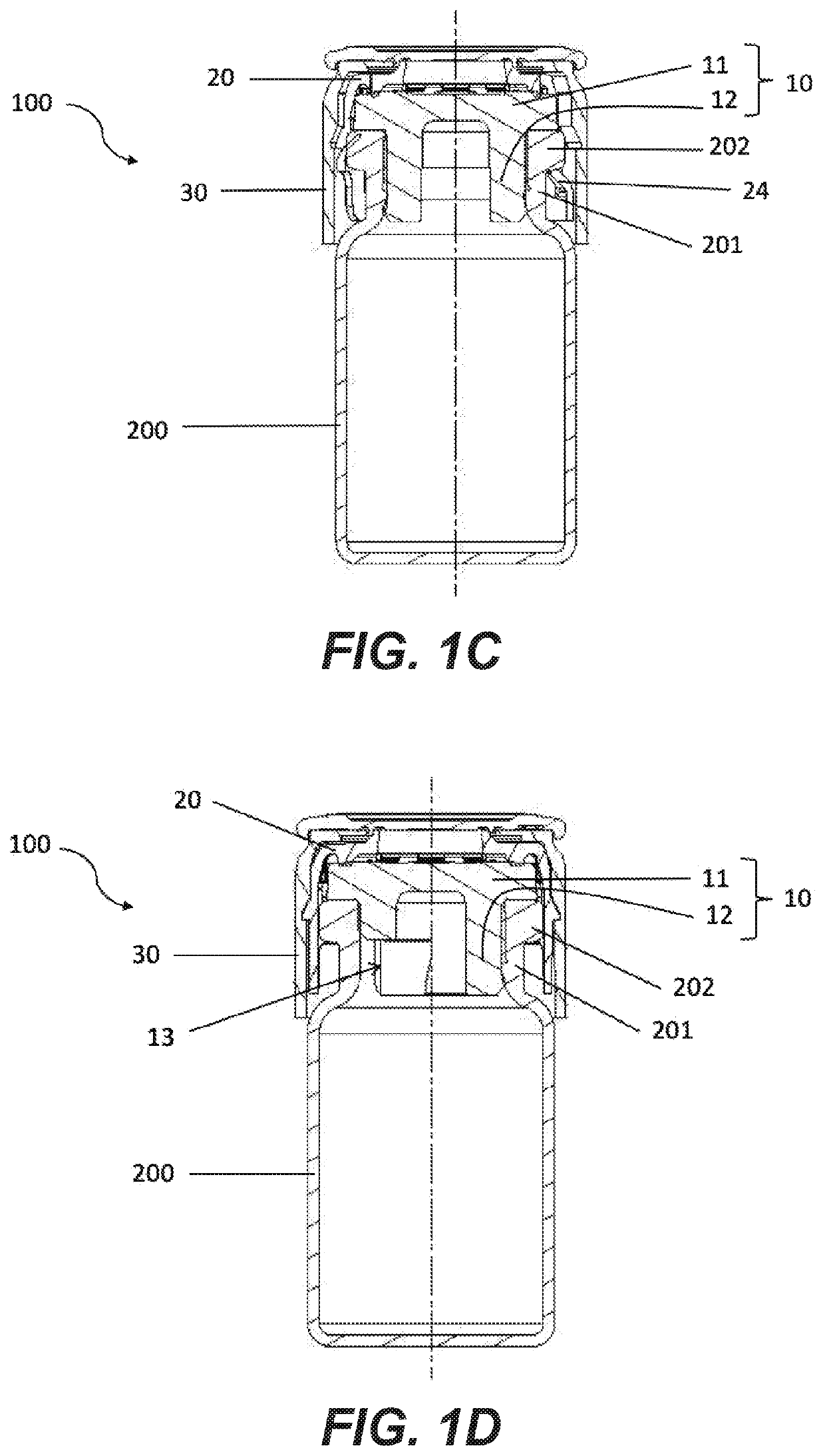
[0036]The present disclosure relates to a locking cap 100 for a container 200 comprising a neck, intended to block a stopper 10 in the neck 201 of the container 200. The container 200 may, in particular, take the form of a bottle, comprising a neck 201 having a circular opening, which ends in a collar 202 that is flared relative to the external periphery of the neck 201. In other words, the external diameter of the collar 202 is greater than the external diameter of the neck 201, as shown in FIGS. 1A and 1B.

[0037]In the field of pharmaceutical applications, there are standards in terms of the internal diameter of the neck 201 of the container 200: 13 mm and 20 mm are examples thereof.

[0038]The stopper 10 has a circular section and a T-shape having a head 11 and a f...


PUM

PropertyMeasurementUnit
forceaaaaaaaaaa
forceaaaaaaaaaa
forceaaaaaaaaaa

Abstract

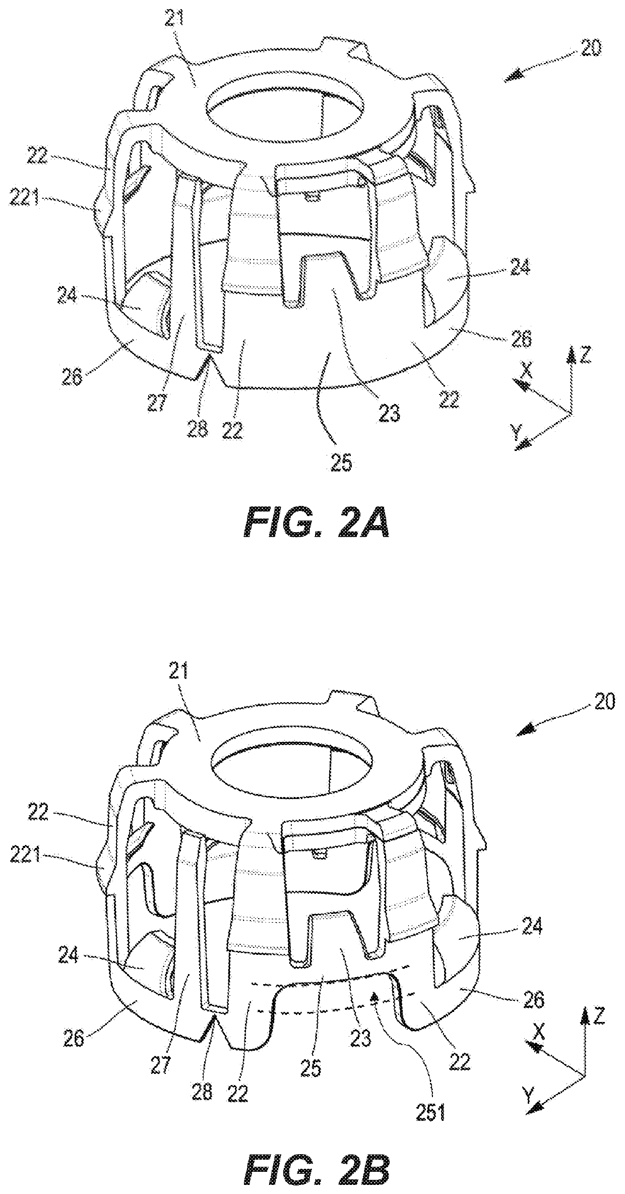
The invention relates to a locking cap for a container comprising a neck, intended to block a stopper in the neck of the container and comprising: an external body having a breakable part, a cage that is configured to fit into and lock axially in the external body, and having a breakable zone, the cage further comprising: an upper ring, a plurality n of branches that are connected to the upper ring and define therewith a generally cylindrical shape, n / 2 first bridges and n / 2 second bridges, each interconnecting two adjacent branches, at least one opening tab, which is supported by a second bridge, which is inclined toward the outside of the cage and is oriented toward the upper ring, the opening tab being adjacent to the breakable zone, which is located on the second bridge.

Description

PRIORITY CLAIM[0001]This application claims the benefit of the filing date of French Patent Application Serial No. FR1907696, filed Jul. 9, 2019, for “Breakable Locking Cap for a Container Comprising a Neck,” the disclosure of which is hereby incorporated herein in its entirety by this reference.TECHNICAL FIELD[0002]The present disclosure relates to a cap for a container comprising a neck, intended to block a stopper in the neck of the container. The present disclosure relates in particular to a locking cap suitable for bottles, for example for pharmaceutical products, requiring the stopper and the cap to be completely removed in order to extract or reconstitute the product.BACKGROUND[0003]EP2814752 is known, which proposes a completely removable device for locking a stopper to a container comprising a neck. This device comprises an outer ring shaped to cover the stopper and surround the upper collar of the neck of the container. It also comprises an annular inner ring that is capab...

Claims


Application Information

Patent Timeline
Patent Type & Authority Applications(United States)
IPC IPC(8): B65D45/30B65D39/00B65D1/02B65D85/00A61J1/14
CPCB65D45/30B65D39/0076A61J1/1412B65D85/70B65D1/023B65D51/20B65D55/024B65D55/063B65D41/28B65D51/241B65D51/18B65D2251/0015B65D2251/0075B65D41/48B65D2401/35B65D45/32B65D55/02
Inventor CLAVEL, MAXIMEREY, GAËTAN
Owner A RAYMOND & CO
Learn More