Driving method and driving device of display panel

Pending Publication Date: 2021-01-14
HKC CORP LTD
View PDF0 Cites 0 Cited by
  • Summary
  • Abstract
  • Description
  • Claims
  • Application Information

AI Technical Summary

Benefits of technology

The present patent proposes a method for driving a display panel to improve color cast without affecting the panel's transparency. The method uses two scanning driving signals that are interspersed to drive sub-pixels on two adjacent rows. By shortening the driving time of one of the scanning signals, there are differences in the charging ability of the sub-pixels on the two rows. This results in a reduction of color cast by using a driving method called high / low voltage interleaving arrangement.

Problems solved by technology

Comparing VA liquid crystal technology with IPS liquid crystal technology, it can be found that VA liquid crystal technology has higher production efficiency and a lower manufacturing cost, but it is worse than IPS liquid crystal technology in optical property performance, and there are obvious optical property defects.
Especially when it is suitable for a large-sized display panel, if the display panel is viewed with a small viewing angle during the driving process of the VA liquid crystal, for example, the lightness of the pixel will vary linearly with voltage if viewed from the front; the lightness of the pixel will quickly saturate with voltage if viewed with a larger viewing angle, resulting in serious deterioration of the image quality of the viewing angle.
Obviously, there is a big difference between the ideal curve and the actual curve, which makes the gray scale which should be presented under a larger viewing angle seriously change due to deterioration, which leads to color cast.
However, the manner of dividing the main pixel and the secondary pixel will solve the color cast problem by spatially giving different driving voltages to the main and secondary pixels, thus causing the design of a metal routing or a Thin Film Transistor (TFT) element again to drive the secondary pixel, which will cause the transmissible open area to sacrifice, which in turn affects the panel transmittance.

Method used


Image

  • Driving method and driving device of display panel
  • Driving method and driving device of display panel
  • Driving method and driving device of display panel

Examples


Embodiment Construction

[0033]It should be understood that the specific embodiments described herein are only for illustrating but not for limiting the present application.

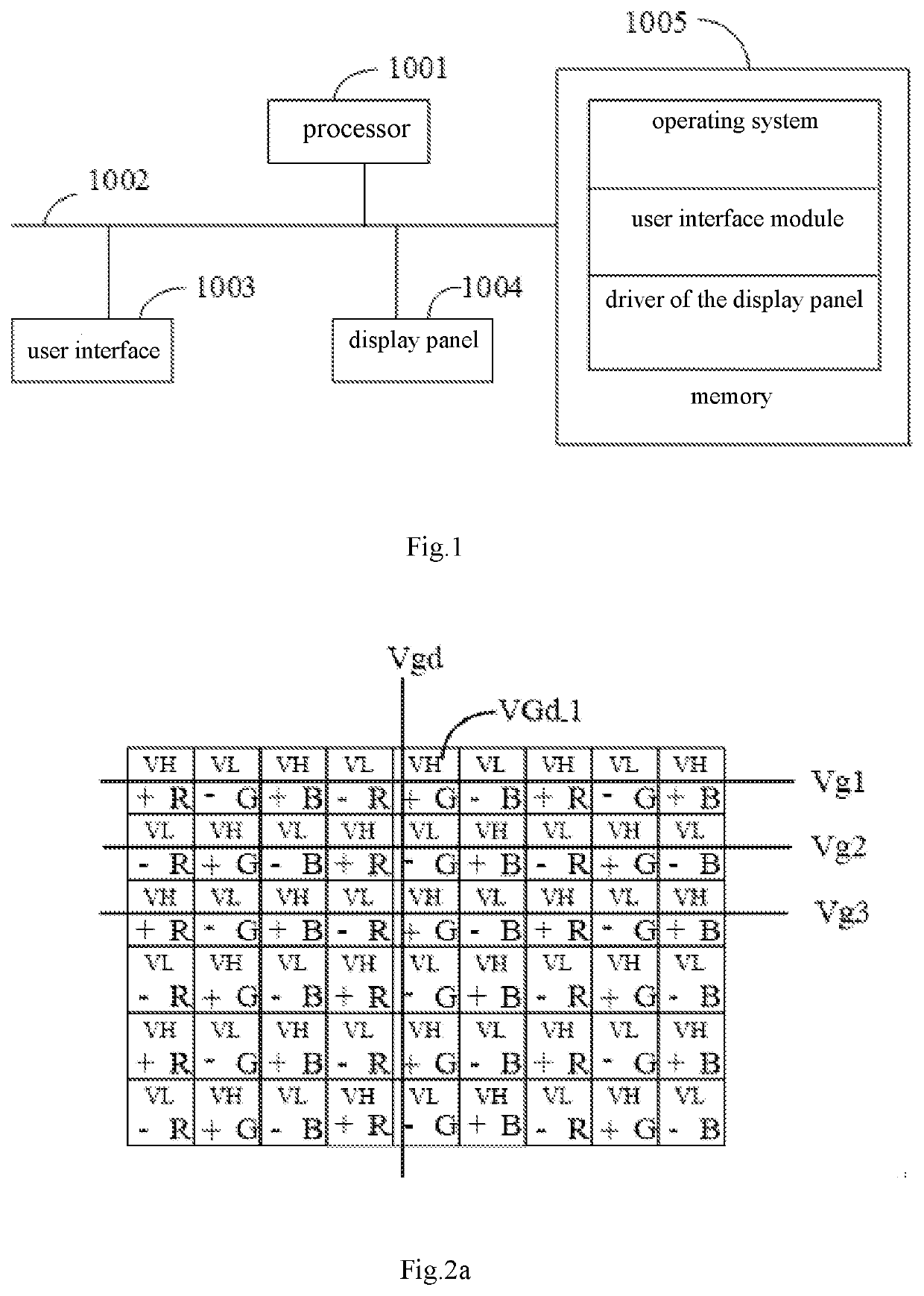
[0034]Referring to FIG. 1, which is a structural schematic diagram of a display panel of a hardware operating environment involved in an implementation of the present application;

[0035]As shown in FIG. 1, the display panel may include a processor 1001, such as a CPU, a communication bus 1002, a user interface 1003, a network interface 1004, and a memory 1005. Wherein the communication bus 1002 is configured to realize connection and communication between the assemblies. The user interface 1003 may include a display, and an input unit such as a keyboard. Alternatively, the user interface 1003 may further include a standard wired interface and a standard wireless interface. The network interface 1004, alternatively, may include a standard wired interface and a standard wireless interface (such as a WiFi interface). The memory 1005 can be a...


PUM


Abstract

Disclosed are a driving method and a driving device of a display panel. The method includes: acquiring a first preset scanning driving signal, a second preset scanning driving signal, and a preset data driving signal, and shortening a driving time of the second preset scanning driving signal corresponding to the preset data driving signal; driving odd-numbered columns of sub-pixels in a first row and even-numbered columns of sub-pixels in a second row by the first preset scanning driving signal, and driving even-numbered columns of sub-pixels in the first row and odd-numbered columns of sub-pixels in the second row in the driving cycle by the second preset scanning driving signal.

Description

CROSS REFERENCE TO RELATED APPLICATIONS[0001]This application is a continuation application of International application with No. PCT / CN2019 / 076216, filed on Feb. 27, 2019, which claims the benefit of Chinese Patent Application No. 201910098294.9, submitted to Patent Office of the People's Republic of China, filed on Jan. 30, 2019 and titled “DRIVING METHOD, DRIVING DEVICE AND DRIVING APPARATUS OF DISPLAY PANEL, AND STORAGE MEDIUM”, the entire contents of which are incorporated by reference in the present application.FIELD OF THE DISCLOSURE[0002]The present disclosure relates to the field of liquid crystal display technologies, and in particular, to a driving method of display panel and a driving device of display panel.BACKGROUND[0003]Most of the current large-size liquid crystal display panels are Vertical Alignment (VA) liquid crystal or In-Plane Switching (IPS) liquid crystal.[0004]Comparing VA liquid crystal technology with IPS liquid crystal technology, it can be found that VA...

Claims


Application Information

Patent Timeline
IPC IPC(8): G09G3/36
CPCG09G3/3677G09G3/3688G09G2300/0452G09G3/3614G09G3/3607G09G2300/0495G09G2310/0224G09G2310/0243
Inventor SHAN, JIANFENG
Owner HKC CORP LTD
Why Eureka
Try Eureka