Method of forming topology-controlled amorphous carbon polymer film

Active Publication Date: 2021-01-21
ASM IP HLDG BV
View PDF0 Cites 174 Cited by
  • Summary
  • Abstract
  • Description
  • Claims
  • Application Information

AI Technical Summary

Benefits of technology

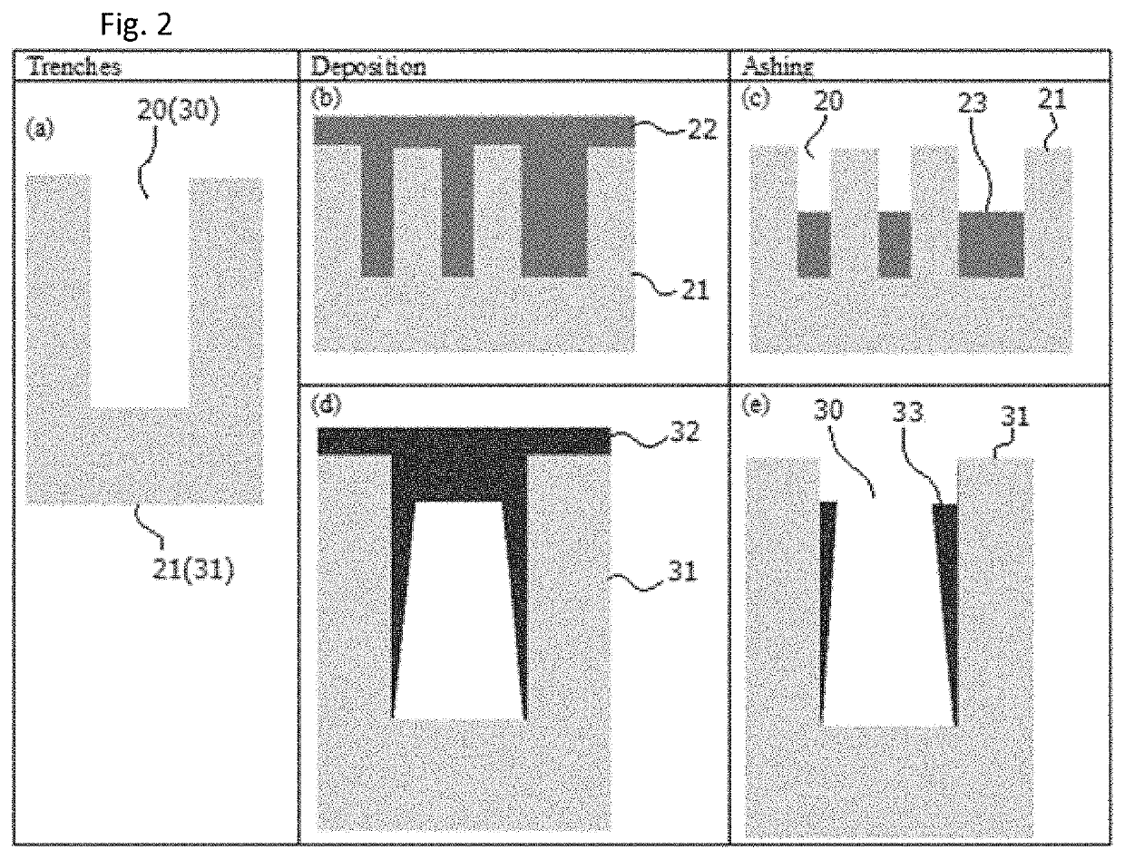
[0010]When the flowability of film is sufficiently low relative to target trenches, bottomless deposition occurs; however, because the film is flowable, even when the film does not reach the bottom of the trench and closes the upper opening of the trench, the film can deposit along the sidewall of the trench to cover the sidewall to a certain depth from the top surface of the substrate. After completion of deposition of the film, by subjecting the film to plasma ashing, the portion of the film closing the opening of the trench can be removed to open the trench, leaving the sidewall film as a spacer. Thereafter, ultradeep hole straight etching can be performed. Since the bottom of the trench is substantially not covered by the film, and the sidewall film can protect the sidewall from being etched during the ultradeep hole straight etching, etching can progress in the depth direction to form an ultradeep straight hole, without degrading CD integrity.

Problems solved by technology

When the flowability of film is sufficiently low relative to target trenches, bottomless deposition occurs; however, because the film is flowable, even when the film does not reach the bottom of the trench and closes the upper opening of the trench, the film can deposit along the sidewall of the trench to cover the sidewall to a certain depth from the top surface of the substrate.

Method used


Image

  • Method of forming topology-controlled amorphous carbon polymer film
  • Method of forming topology-controlled amorphous carbon polymer film
  • Method of forming topology-controlled amorphous carbon polymer film

Examples


example 1

[0073]An amorphous carbon polymer film was deposited on a Si substrate (having a diameter of 300 mm and a thickness of 0.7 mm) having trenches with an opening of approximately 20 nm, which had a depth of approximately 200 nm (an aspect ratio was approximately 10), by PEALD-like process in a bottom-up manner under the same conditions as in Reference Example 1 except that the deposition cycle was repeated 210 times (p=210) so that the film accumulated on the top surface of the substrate to a thickness of 100 nm. Thereafter, ashing was continuously conducted using a mixture of O2 and Ar in the same manner as in Reference Example 1 except that RF time was shortened to 90 seconds so as to form film structures having bottom-only topology wherein the film was ashed to a depth of 181 nm from the top surface of the substrate.

[0074]FIG. 9 shows STEM photographs of cross-sectional views of the trenches subjected to the bottom-up deposition, wherein (a) represents trenches at completion of depo...

example 2

[0075]An amorphous carbon polymer film was deposited on a Si substrate having trenches in the same manner as in Example 1 except that ashing time varied.

[0076]FIG. 10 shows STEM photographs of cross-sectional views of the trenches subjected to bottom-up deposition (full fill), wherein raw (a) represents a mixture of wide trenches and narrow trenches having different widths (the scale represents 300 nm), raw (b) represents intermediate trenches (the scale represents 60 nm), and raw (c) represents wide trenches with slight difference in width (the scale represents 60 nm), column (1) represents the trenches with full-fill deposition (210 cycles of deposition) prior to ashing, column (2) represents the trenches after ashing for 105 seconds, column (3) represents the trenches after ashing for 129 seconds, and column (4) represents the trenches after ashing for 165 seconds.

[0077]FIG. 11 shows STEM photographs of cross-sectional views of the trenches subjected to bottom-up deposition, wher...

reference example 2

[0079]An amorphous carbon polymer film was deposited on a Si substrate (having a diameter of 300 mm and a thickness of 0.7 mm) having trenches with an opening of approximately 150 nm, which had a depth of approximately 2500 nm (an aspect ratio was approximately 17), by PEALD-like process in a bottomless manner under the same conditions as in Reference Example 1 except that the deposition cycle was repeated 350 times (p=350) so that the film accumulated on the top surface of the substrate to a thickness of 160 nm.

[0080]The bottomless deposition has been confirmed by STEM photographs of cross-sectional views of trenches subjected to the bottomless deposition, which include (a) a view of a series of the film-deposited trenches, (b) an enlarged view of a top portion of one of the trenches, (c) an enlarged view of a bottom portion of the trench, and (d) an enlarged view of sidewalls of the trench. It has been confirmed that although the trenches are not fully filled with the film as obse...


PUM

PropertyMeasurementUnit
depthaaaaaaaaaa
aspect ratioaaaaaaaaaa
aspect ratiosaaaaaaaaaa

Abstract

A method of forming a topology-controlled layer on a patterned recess of a substrate, includes: (i) depositing a Si-free C-containing film having filling capability on the patterned recess of the substrate by pulse plasma-assisted deposition to fill the recess in a bottom-up manner or bottomless manner; and (ii) subjecting the bottom-up or bottomless film filled in the recess to plasma aching to remove a top portion of the filled film in a manner leaving primarily or substantially only a bottom portion of the filled film or primarily or substantially only a sidewall portion of the filled film.

Description

CROSS-REFERENCE TO RELATED APPLICATIONS[0001]This application claims the benefit of U.S. Provisional Application No. 62 / 876,588, filed on Jul. 19, 2019, in the United States Patent and Trademark Office, the disclosure of which is incorporated herein in its entirety by reference.BACKGROUND OF THE INVENTIONField of the Invention[0002]The present invention generally relates to a method of forming a topology-controlled amorphous carbon film on a patterned recess of a substrate.Description of the Related Art[0003]In processes of fabricating integrated circuits such as those for shallow trench isolation, inter-metal dielectric layers, passivation layers, etc., it is often necessary to fill trenches (any recess typically having an aspect ratio of one or higher) with insulating material. However, with miniaturization of wiring pitch of large scale integration (LSI) devices, void-free filling of high aspect ratio spaces (e.g., AR≥3) becomes increasingly difficult due to limitations of existi...

Claims


Application Information

Patent Timeline
Patent Type & Authority Applications(United States)
IPC IPC(8): H01L21/02
CPCH01L21/02115H01L21/0234H01L21/02274H01L21/76224H01L21/76825H01L21/02118H01L21/0228H01L21/02271H01L21/56H01L21/31122C23C16/045C23C16/56C23C16/26C23C16/45536H01L21/31116
Inventor BLANQUART, TIMOTHEE JULIEN VINCENT
Owner ASM IP HLDG BV
Why Eureka
Try Eureka