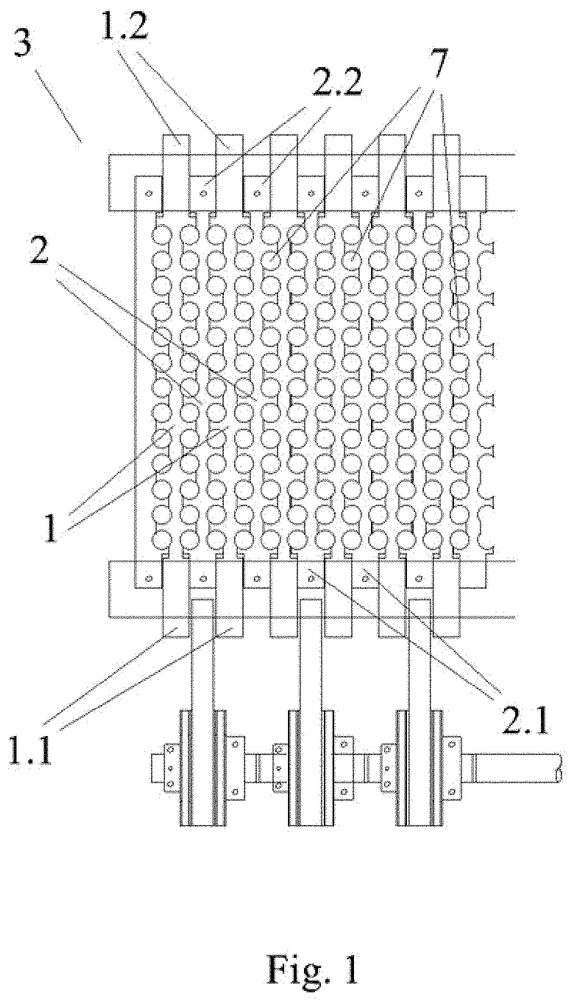
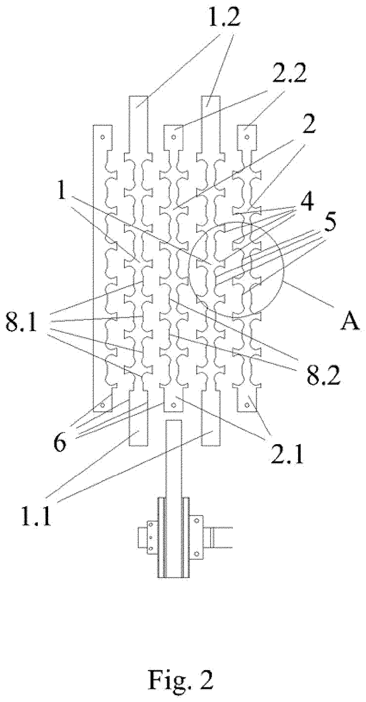
[0040]In view of the figures that have been provided, it can be observed how, in a preferred embodiment of the invention, the cracking-shelling mechanism (3) for nuts with a hard or soft shell proposed herein for nut shelling machines comprises a plurality of first longitudinal blocks (1) parallel to one another, with a first end (1.1) secured to means for reciprocating movement in both directions according to the longitudinal axis thereof, and a plurality of second longitudinal blocks (2) parallel to the first longitudinal blocks and arranged in an alternating and adjacent manner with respect to same.
[0041]All the blocks (1, 2) have first and second ends (1.1, 1.2, 2.1, 2.2), respective lower and upper bases, and two sides (6). Likewise, between the sides (6) of each first and second block (1, 2) there is formed a plurality of tapered vertical through holes (7) between the upper and lower bases of the blocks.
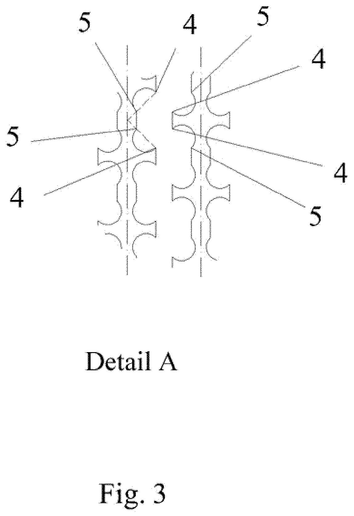
[0042]In this mechanism (3) the facing sides (6) between each first and second block (1, 2) further comprise a plurality of first and second notches (8.1, 8.2), respectively, complementary to one another and in a staggered arrangement, such that each first notch (8.1) is associated with at least a second notch (8.2) and forms a cracking hole (7) with each second notch (8.2) associated with it.
[0043]Having said that, as shown in FIGS. 1, 2, and 4, each first block (1) has a first notch (8.1) arranged at a first end (1.1) thereof which is associated with a single second notch (8.2) of the second block (2), and therefore that first notch (8.1) forms a single hole (7). The remaining first notches (8.1) of the first blocks (1) are associated with two second notches (8.2) and form a hole (7) with each of them, therefore each of these first notches (8.1) forms two holes (7) each.
[0044]In the case of the second notches (8.2), since they are in a staggered arrangement with respect to the first notches (8.1), the same occurs but opposite to what occurs in the first block, i.e., it is the second notch (8.2) arranged at the second end of each second block (2) which is associated with a single first notch (8.1) and therefore forms a single hole (7), whereas the remaining second notches (8.2) are associated with two first notches (8.1) and therefore form two holes (7) each.
[0045]As can be observed in FIG. 3, these first and second notches (8.1, 8.2) have, for each hole (7), first and second vertexes (4, 5) demarcating the contour thereof, arranged such that the first vertex (4) is farther away from the longitudinal axis of the corresponding block than the second vertex (5), and each first and second vertex (4, 5) of a hole (7) is aligned forming a specific angle with respect to said longitudinal axis.
[0046]Likewise, as shown in FIGS. 1, 2, and 5.1, in a standby position of the first block (1) each first and second vertex (4, 5) of each first notch (8.1) is arranged so as to coincide with second and first vertexes (5, 4), respectively, of a second notch (8.2), configuring a closed curved shape.
[0047]As can be observed in FIG. 5,2, depicting the hole (7) after the movement of the first block (1), the first and second vertexes (4, 5) of the first notch (8.1) are moved with respect to the respective corresponding second and first vertexes (5, 4) of the second notch, such that the first vertex (4) of both first and second notches (8.1, 8.2) is arranged in both cases inside the hole (7), but at the same time it is significantly separated from the area where the nut is located, therefore the risk of the nut being damaged by said vertexes is significantly reduced.
[0048]FIGS. 6.1 and 6.2 show the position of the vertexes in the case of standby and of movement, respectively, of the first block in a conventional mechanism of the state of the art, and as can be observed, the first and second vertexes are much more exposed and closer to the area where the nut is located in this case, and this is why nuts today present a high percentage of damage and scratching.
[0049]In this preferred embodiment of the invention, the first and second vertexes (4, 5) demarcating the contour of a hole (7) in each first and second notch (8.1, 8.2) are aligned forming an angle comprised between 30° and 60° or between 120° and 150° with respect to the longitudinal axis of the corresponding block.
[0050]Likewise, in this embodiment at least a first and/or a second notch (8.1, 8.2) forms respective holes (7) with respective second and/or first notches (8.2, 8.1), respectively, and the first and second vertexes (4, 5) demarcating the contour of a hole (7) are arranged in a manner symmetrical to the first and second vertexes (5, 4) demarcating the contour of the other hole (7) of one and the same notch.
[0051]Therefore, as shown in FIGS. 1 and 2, in the first notches (8.1) of each first block (1) having a single hole (7), the latter has first and second vertexes (4, 5) forming an angle comprised between 30 and 60° or between 120° and 150°, according to the side of the first block (1) being considered.
[0052]The remaining first notches have first and second vertexes (4, 5) with the same inclination as the vertexes of the first notch (8.1) arranged at the first end (1.1), and a second hole (7), the first and second vertexes (4, 5) of which are arranged symmetrically with respect to the aforementioned vertexes, therefore if the aforementioned vertexes form an angle comprised between 30° and 60°, the other vertexes form an angle comprised between 120° and 150°, and vice versa.
[0053]In this preferred embodiment of the invention, the sides (6) of each block are symmetrical with respect to a longitudinal central plane thereof. The cracking holes (7) will thereby be formed in a manner symmetrical to each side of the block.
[0054]According to another aspect, in this preferred embodiment of the invention the second blocks (2) comprise means for regulating the position according to the direction of an axis perpendicular to same and parallel to the longitudinal axis of the holes. It is thereby possible to modify their position in one direction or the other, achieving a reduction or increase in the size of cracking holes (7).
[0055]Namely in this case, the means for regulating the position of said second blocks (2) are independent for each of them, so, for example, the size of the holes (7) may be established by areas, according to the size of the nut reaching each of them from prior screening. Nevertheless, in other cases the regulating means may be common to all the second blocks (2).
[0056]As shown in FIGS. 1 to 4, in this preferred embodiment of the invention the means for reciprocating movement of the first blocks (1) are formed by a respective connecting rod (9) with an eccentric axis of rotation. In this case, every two first blocks (1) are connected to one and the same connecting rod (9), so two first blocks (1) have one and the same movement, which may be identical to or different from the movement of other first blocks (1) connected to another connecting rod (9).
[0057]Having said that, it can be observed in FIG. 4 that first blocks (1), the ones located in the center of the figure are moved in one direction, whereas first blocks (1) arranged at the ends in the figure are moved in the opposite direction. The respective holes (7) increase and decrease in size based on their position with respect to the corresponding block and on the direction of movement thereof. When the holes (7) increase in size, on one hand the nut is allowed to enter the hole (7) and at the same time, if a nut kernel has previously been cracked, it is allowed to exit same through the lower part, whereas when the holes (7) decrease in size, the kernel is cracked.
[0058]As a result of the shape and arrangement of the first and second notches (8.1, 8.2), while one hole of a specific notch increases in size, the other hole thereof decreases in size, such that there is always a number of holes that allow the nut to enter while at the same time there is another number of holes which are cracking the nut at that time. Therefore accumulations are not generated, and effectiveness of the mechanism is increased.
[0059]In other preferred embodiments of the invention, the means for reciprocating movement of the first blocks (1) are formed by a respective pneumatic piston, a respective electromagnetic mechanism, or a similar mechanism, capable of generating this type of movement.
[0060]The described embodiment constitutes only one example of the present invention; therefore, the specific details, terms, and expressions used in the present specification should not be considered as limiting, but rather must be understood solely as a basis for the claims and as a representative basis which provides a comprehensible description as well as sufficient information for one skilled in the art to apply the present invention.