
Conbined Tubular Metal Oxide Varistor and Gas Discharge Tube

a technology of metal oxide varistor and gas discharge tube, which is applied in the direction of resistor details, spark gap details, overvoltage protection resistors, etc., can solve the inconvenience of not being able to absorb an unlimited number of surges, mov degrade with use, and inconvenience of mov device short circui

Active Publication Date: 2021-02-04
DONGGUAN LITTELFUSE ELECTRONICS CO LTD
View PDF0 Cites 0 Cited by
  • Summary
  • Abstract
  • Description
  • Claims
  • Application Information

AI Technical Summary

Benefits of technology

The patent proposes a solution that combines a GDT device and a MOV device to protect electrical elements. This combination has the advantage that it has a lower capacitance compared to a separate GDT and MOV device. However, the size of the combined device is significantly larger, limiting its use in space-saving conditions. The technical effect of this solution is to improve protection against overvoltage and current spikes while maintaining a compact size.

Problems solved by technology

MOV devices are generally fast acting, which is very desirable in certain applications, but with the inconvenience of not being able to absorb an unlimited number of surges.
That is, MOVs degrade with use and in the end fail.
Furthermore, there is the inconvenience that the MOV device may short circuit in case of malfunction, necessitating some other type of protection against this inconvenience.
With regard to GDT devices, which are generally slower acting devices that function by producing an electric arc in their interior when nominal voltage is surpassed, impedance between their terminals during use diminishes drastically, potentially causing a short circuit.
Furthermore, GDT devices have relatively small capacitance.
However, this solution has significant size constraints, which limit use in space saving condition.

Method used


Image

  • Conbined Tubular Metal Oxide Varistor and Gas Discharge Tube
  • Conbined Tubular Metal Oxide Varistor and Gas Discharge Tube
  • Conbined Tubular Metal Oxide Varistor and Gas Discharge Tube

Examples


Embodiment Construction

[0020]Embodiments in accordance with the present disclosure will now be described more fully hereinafter with reference to the accompanying drawings. The device / circuit may be embodied in many different forms and should not be construed as being limited to the embodiments set forth herein. Rather, these embodiments are provided so that this disclosure will be thorough and complete, and will fully convey the scope of the system and method to those skilled in the art.

[0021]For the sake of convenience and clarity, terms such as “top,”“bottom,”“upper,”“lower,”“vertical,”“horizontal,”“lateral,” and “longitudinal” will be used herein to describe the relative placement and orientation of various components and their constituent parts. Said terminology will include the words specifically mentioned, derivatives thereof, and words of similar import.

[0022]As used herein, an element or operation recited in the singular and proceeded with the word “a” or “an” should be understood as not excludin...


PUM

PropertyMeasurementUnit
break-over voltagesaaaaaaaaaa
trigger voltageaaaaaaaaaa

Abstract

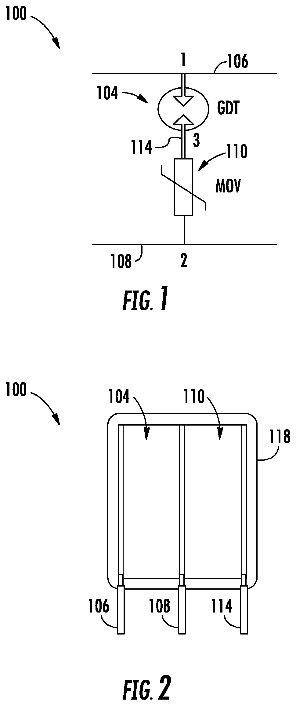
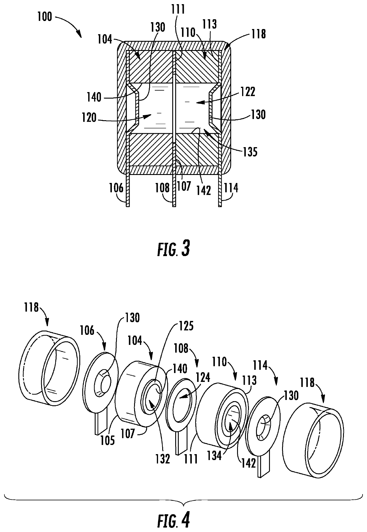
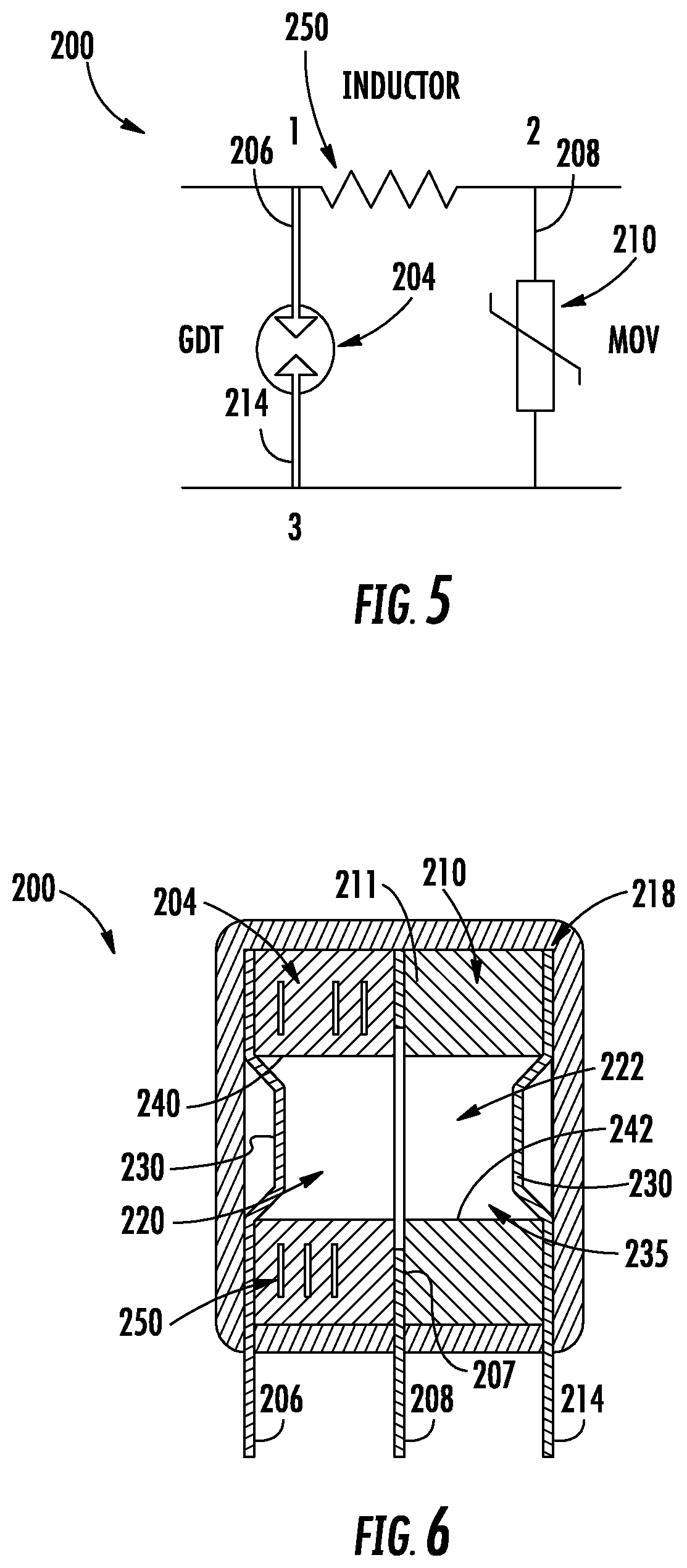
Provided herein are protection devices having a tubular ceramic part and a tubular metal oxide varistor (MOV) electrically coupled in series or parallel. In some embodiments, the tubular ceramic part is connected between a first electrode and a second electrode, and the tubular MOV is connected between the second electrode and a third electrode. In some embodiments, the tubular ceramic part and the tubular MOV have a same or similar shape and / or outer circumference. The protection device further includes an enclosure surrounding the tubular ceramic part and the tubular MOV, wherein the first electrode, the second electrode, and the third electrode each have leads extending outside the enclosure. In some embodiments, the tubular MOV includes a central cavity aligned with a central cavity of the tubular ceramic part, wherein the central cavity of the tubular MOV MOV and the central cavity of the tubular ceramic part contain an inert gas.

Description

FIELD OF THE DISCLOSURE[0001]The disclosure relates generally to the protection of electrical and electronic circuits and equipment from power surges and, more particularly, to a combined tubular metal oxide varistor and gas discharge tube.BACKGROUND OF THE DISCLOSURE[0002]A variety of devices are available on the market that are designed to protect devices that are susceptible to damage by voltage surge when the voltage applied between power terminals exceeds a maximum acceptable threshold. For example, some prior art approaches include metal oxide varistors (MOVs), based on semiconductors and the like, as well as gas discharge tube (GDT) devices. MOV devices are generally fast acting, which is very desirable in certain applications, but with the inconvenience of not being able to absorb an unlimited number of surges. That is, MOVs degrade with use and in the end fail. The number of times an MOV device shall function correctly depends on the energy absorbed each time it functions. ...

Claims


Application Information

Patent Timeline
Patent Type & Authority Applications(United States)
IPC IPC(8): H01C7/12H01J17/34H01C1/024H01C1/14
CPCH01C7/12H01C1/14H01C1/024H01J17/34H01C7/10H01T1/16
Inventor SHU, XIATANG, HAILANGXIAO, YANJING
Owner DONGGUAN LITTELFUSE ELECTRONICS CO LTD
Learn More