
Insulation of winding ends of a stator winding

a technology of winding end and stator, which is applied in the direction of windings, solid insulation, magnetic circuit shapes/forms/construction, etc., can solve the problems of inefficiency of fully automatic production lines, and achieve the effect of compact cross-section of winding ends

Active Publication Date: 2021-02-04
SIEMENS AG
View PDF0 Cites 0 Cited by
  • Summary
  • Abstract
  • Description
  • Claims
  • Application Information

AI Technical Summary

Benefits of technology

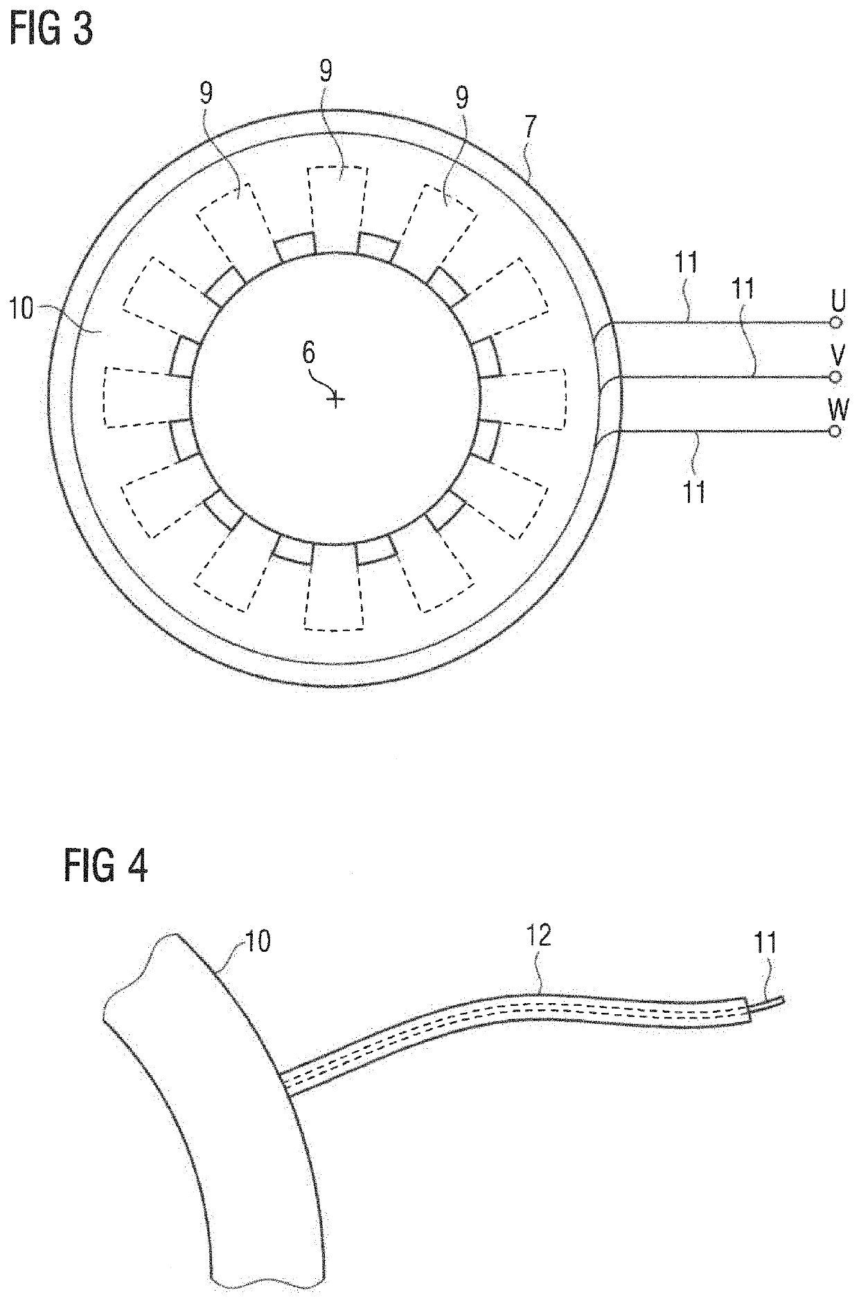
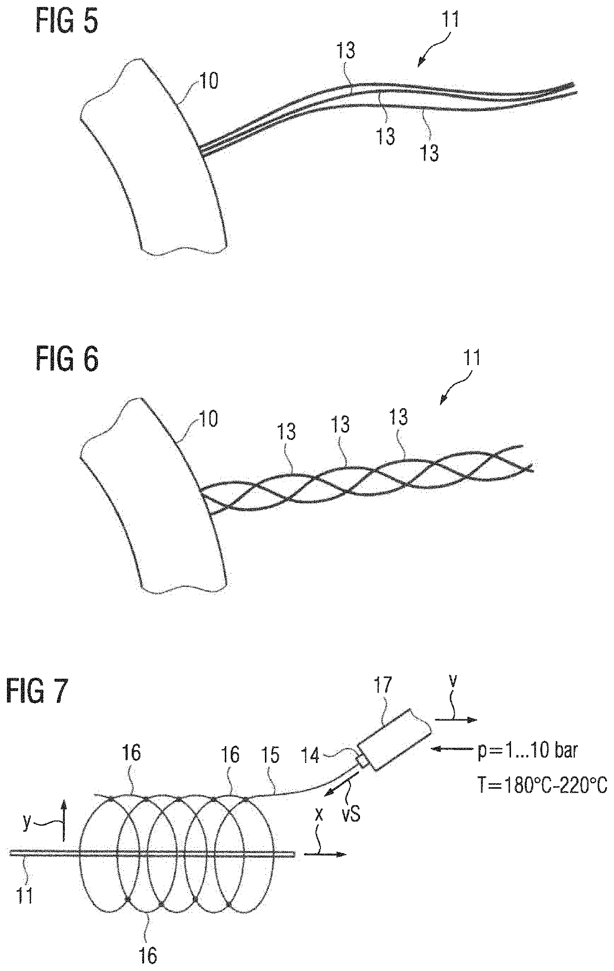
The present invention provides a way to easily encase winding ends with a completely closed insulation layer. The nozzle moves along the longitudinal extent of the winding end in two ways: a continuous movement with a fixed speed and an additional movement with an amplitude and frequency. The fixed speed is less than the product of amplitude and frequency. This allows for easy encasing of the winding end. The winding end can also have multiple wires twisted with each other, keeping the cross-section compact.

Problems solved by technology

This plurality of different variants often renders a fully-automated production line inefficient.

Method used


Image

  • Insulation of winding ends of a stator winding
  • Insulation of winding ends of a stator winding
  • Insulation of winding ends of a stator winding

Examples


Embodiment Construction

[0034]Throughout all the figures, same or corresponding elements may generally be indicated by same reference numerals. These depicted embodiments are to be understood as illustrative of the invention and not as limiting in any way. It should also be understood that the figures are not necessarily to scale and that the embodiments may be illustrated by graphic symbols, phantom lines, diagrammatic representations and fragmentary views. In certain instances, details which are not necessary for an understanding of the present invention or which render other details difficult to perceive may have been omitted.

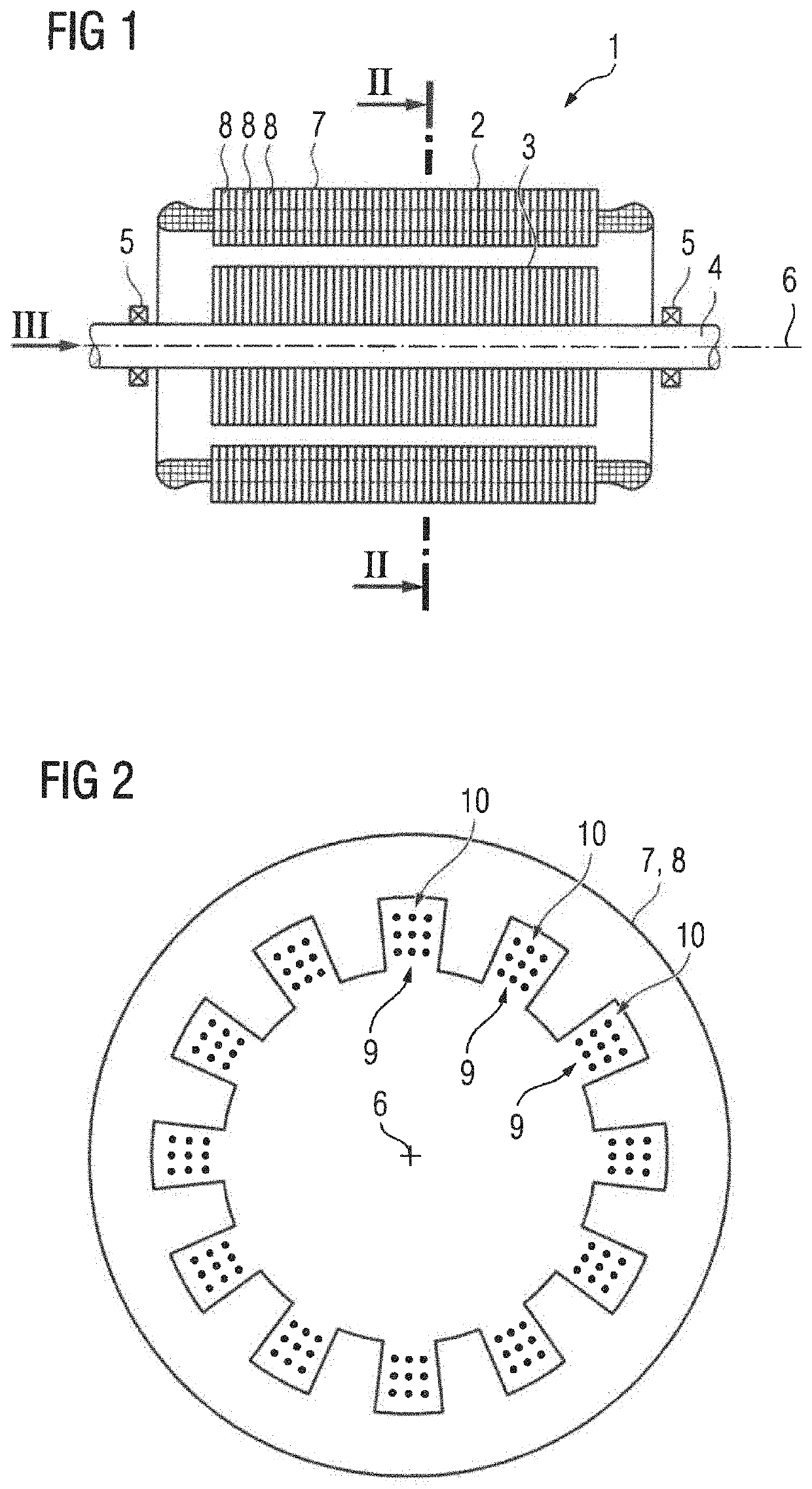
[0035]Turning now to the drawing, and in particular to FIG. 1, there is shown a sectional view of an electric machine according to the present invention, generally designated by reference numeral 1 and including a stator 2. The electric machine 1 can be embodied as a linear electric machine. Normally, however, the electric machine 1 is configured as a rotating electric machine and ...


PUM

PropertyMeasurementUnit
pressureaaaaaaaaaa
pressureaaaaaaaaaa
temperatureaaaaaaaaaa

Abstract

A stator of an electric machine includes a laminated core having slots for receiving windings of a multiphase winding system. The windings have winding ends, which are encased with an insulator across a partial length. In order to encase the winding ends with the insulator, a strand of a thermoplastic material is extruded onto the winding ends via a nozzle. During extrusion, the nozzle is moved relative to the winding end along the longitudinal extent thereof and an oscillating movement of the nozzle transversely to the longitudinal extent of the winding end overlays the movement along the longitudinal extent. As a result the thermoplastic material lies on the winding end and around the respective winding end in the form of loops.

Description

CROSS-REFERENCES TO RELATED APPLICATIONS[0001]This application claims the priority of European Patent Application, Serial No. 19189800.6, filed Aug. 2, 2019, pursuant to 35 U.S.C. 119(a)-(d), the disclosure of which is incorporated herein by reference in its entirety as if fully set forth herein.BACKGROUND OF THE INVENTION[0002]The present invention relates to a method for the production of a stator of an electric machine, to such a stator, and to an electric machine which includes such a stator.[0003]The following discussion of related art is provided to assist the reader in understanding the advantages of the invention, and is not to be construed as an admission that this related art is prior art to this invention.[0004]Electric machines are built with a very high number of different designs. For instance, individual manufacturers in the field of low voltage industrial motors often offer more than 1000 different designs. This plurality of different variants often renders a fully-a...

Claims


Application Information

Patent Timeline
Patent Type & Authority Applications(United States)
IPC IPC(8): H02K15/10H02K1/16H02K3/48H02K15/12H02K3/30
CPCH02K15/105H02K1/16H02K3/14H02K15/12H02K3/30H02K3/48H02K3/38H02K15/0068H02K2203/06
Inventor BÜTTNER, KLAUSKATZENBERGER, TOBIASKIRCHNER, KLAUSPLOCHMANN, BASTIANWARMUTH, MATTHIAS
Owner SIEMENS AG
Learn More