A method for Preparing an Insertion Site for a Cannula on a Skin of a Patient, a Skin Cover Unit Therefore and Its Use

a skin cover unit and insertion site technology, applied in the field of ultrasonic transparent surgical skin cover units, can solve the problems of inferior ultrasonic transmission, insufficient upright position of the upright wall, and inability to work properly in practice, and achieve good skin contact

Pending Publication Date: 2021-02-11
US ENOVACOR APS
View PDF0 Cites 1 Cited by
  • Summary
  • Abstract
  • Description
  • Claims
  • Application Information

AI Technical Summary

Benefits of technology

[0025]For example, if the sheet is made of a thin polymer film, the film itself may readily attach to the skin and follow the contour of the skim even without glue. The principle is similar to the attachment properties of kitchen wrap film. However, for such thin and flexible film, a stable frame is an advantage in that the stable frame gives the necessary stability for not only holding the film but also the wall, and the film can be made sufficiently thin for good skin contact.
[0026]In order to provide a good contact between the ultrasonic probe and the flexible sheet of the window it is often advantageous to use an ultrasonic fluid, typically a gel. This gel is applied to the ultrasonic-tra

Problems solved by technology

Although, the principle as disclosed in the application US2013/0289404 appears theoretically sound, it does not work properly in practice.
This is so because a film stiff enough to hold the wall upright does have a tendency to not readily attach closely to the skin of the patient with the consequence of inferior ultrasonic transmission.
On the other hand, making the film flexible enough

Method used


Image

  • A method for Preparing an Insertion Site for a Cannula on a Skin of a Patient, a Skin Cover Unit Therefore and Its Use
  • A method for Preparing an Insertion Site for a Cannula on a Skin of a Patient, a Skin Cover Unit Therefore and Its Use
  • A method for Preparing an Insertion Site for a Cannula on a Skin of a Patient, a Skin Cover Unit Therefore and Its Use

Examples


Embodiment Construction

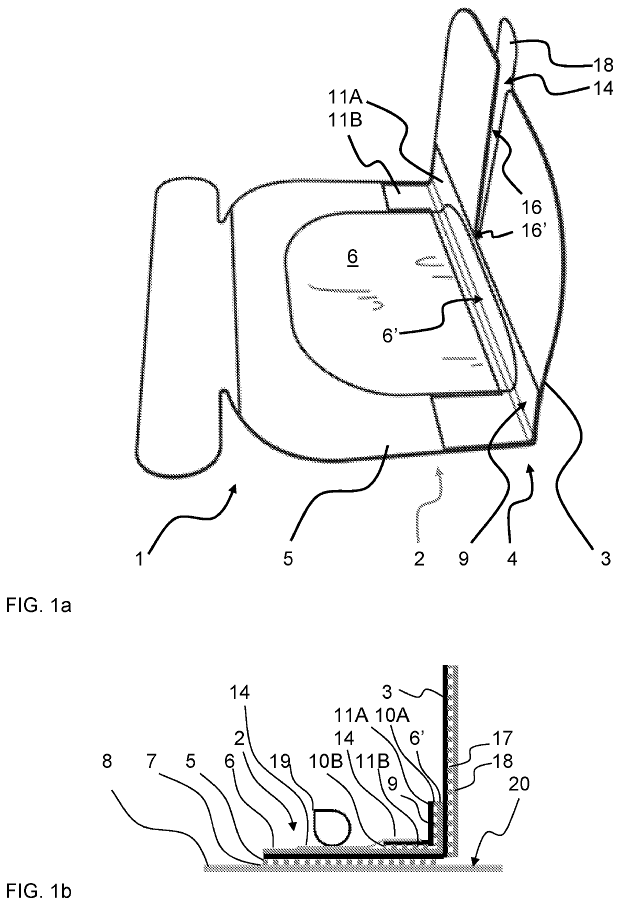
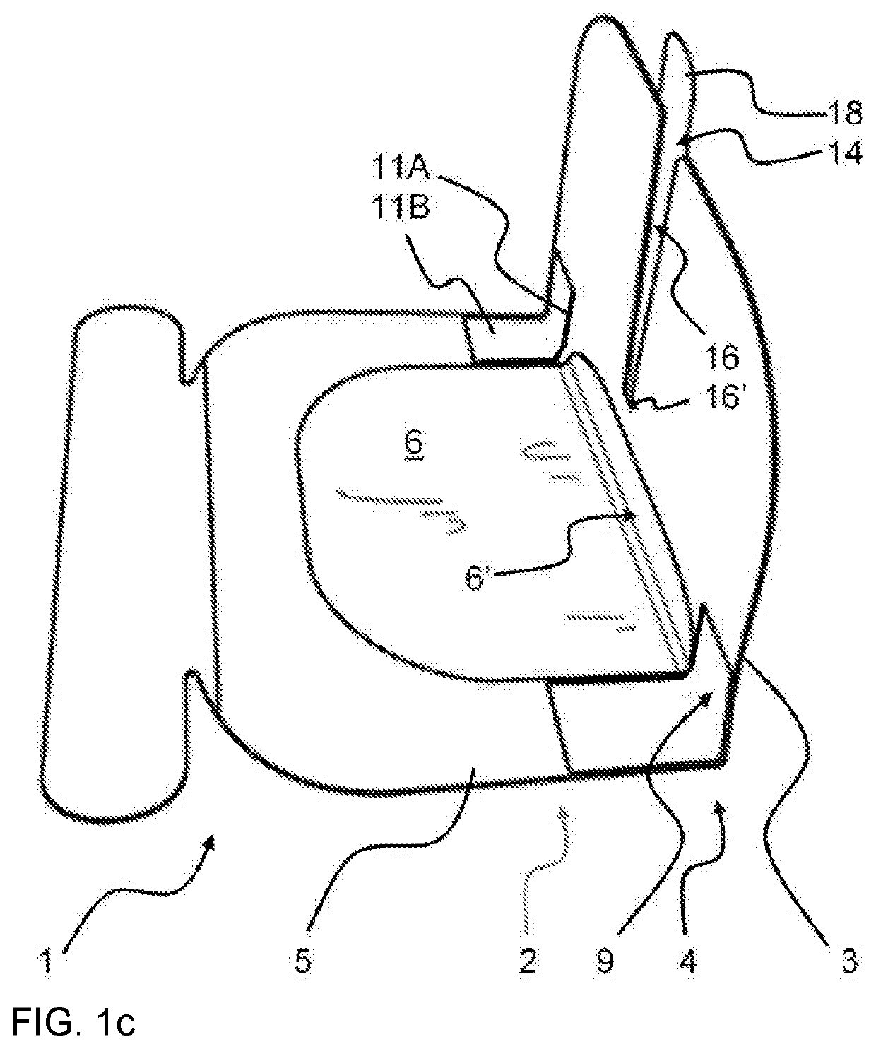
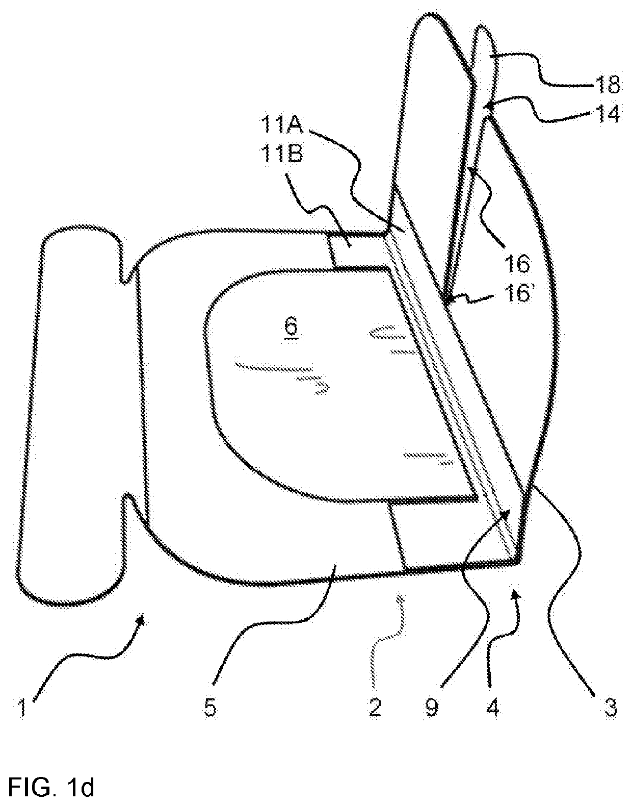
[0047]FIG. 1a and FIG. 1b are images of two alternative skin cover units 1 and FIG. 1c a principle sketch of the cover units 1. The cover unit 1 comprises a window 2 and a wall 3 in extension of the window 2. The wall 3 is connected to the window 2 by a bending region 4 for orienting the wall 3 into an angled orientation relatively to the window 2. The window 2 comprises a stabilizing frame 5 and an ultrasonic-transparent flexible sheet 6, typically polymer film, on or within the frame 5, or at least partially within the frame, for ultrasonic investigation of the insertion site 20 by an ultrasonic probe 19. The flexible sheet 6 is attached to and supported by the frame 5. Further, the flexible sheet 6 comprises an adhesive layer 7 on a first side of the flexible sheet 6 for gluing the window 2 onto the skin 8 of the patient.

[0048]In FIG. 1b, the flexible sheet 6 is shown as placed on the frame-side that is remote from the skin 8, however, it could alternatively be provided inside th...


PUM


Abstract

An insertion site for a cannula (23) on a skin (8) of a patient is prepared by applying a skin cover unit (1) of the type comprising a window (2) and a wall (3) in extension of the window (2) and connected to the window (2) by a bending region (4) for bending the wall (3) into an angled orientation relatively to the window (2); wherein the win-dow (2) comprises a stabilizing frame (5) and an ultrasonic-transparent flexible sheet (6) within the frame (5). The flexible sheet (6) is glued onto the skin (8) of the patient for ultrasonic investigation of the insertion site through the flexible sheet (6). By bending the bending region (4), the angular orientation of the wall (3) is adjusted into an approximately perpendicular orientation relatively to the window (2) for separating the insertion site from the flexible sheet (6) by the wall (3). The cover unit (1) in or at the bending region (4) comprises a stabilizer (9) that is configured for maintaining the angled orientation between the wall (3) and the window (2) by a stabilizing action of the stabilizer (9).

Description

FIELD OF THE INVENTION[0001]The present invention relates to an ultrasonic-transparent surgical skin cover unit for use when inserting a puncture device, such as a cannula, electrode or probe, into a human body, for example into a vein or artery. The present invention relates in particular to procedures involving an ultrasonic device for visualisation of the exact location for the puncturing with the puncture device.BACKGROUND OF THE INVENTION[0002]When a cannula is inserted into a part of a body, for example a blood vessel of an arm or leg, the insertion can be optimized by visualising the blood vessel and the cannula using ultrasonic visualization.[0003]U.S. Pat. No. 9,393,381 and the corresponding patent application US2013 / 0289404 disclose a skin cover unit for this purpose. The skin cover unit comprises an ultrasonic-transparent window, made of polymer film, which is glued onto the skin adjacent to the puncture site and onto which an ultrasonic probe is placed for imaging the pu...

Claims


Application Information

Patent Timeline
IPC IPC(8): A61B17/34A61F13/02A61B8/08
CPCA61B17/3403A61F13/023A61M2025/0273A61B2017/3413A61B8/0841A61M25/02A61B8/00A61F13/00A61M25/01A61B8/4281A61F2013/00182A61M2025/0266A61F2013/00412A61B90/04A61B2017/3407A61B2017/00924
Inventor BENDTSEN, THOMAS FICHTNERSLOTH, ERIKKNUDSEN, LARSBUCHALTER, NEAL JOSEPH
Owner US ENOVACOR APS
Why Eureka
Try Eureka