
Temperature-controlled chemical delivery system and reactor system including same

a chemical delivery system and temperature control technology, applied in the direction of chemically reactive gases, coatings, crystal growth processes, etc., can solve the problems of unsatisfactory condensation in the delivery path, precursor or reactant decomposition,

Pending Publication Date: 2021-02-11
ASM IP HLDG BV
View PDF11 Cites 158 Cited by
  • Summary
  • Abstract
  • Description
  • Claims
  • Application Information

AI Technical Summary

Benefits of technology

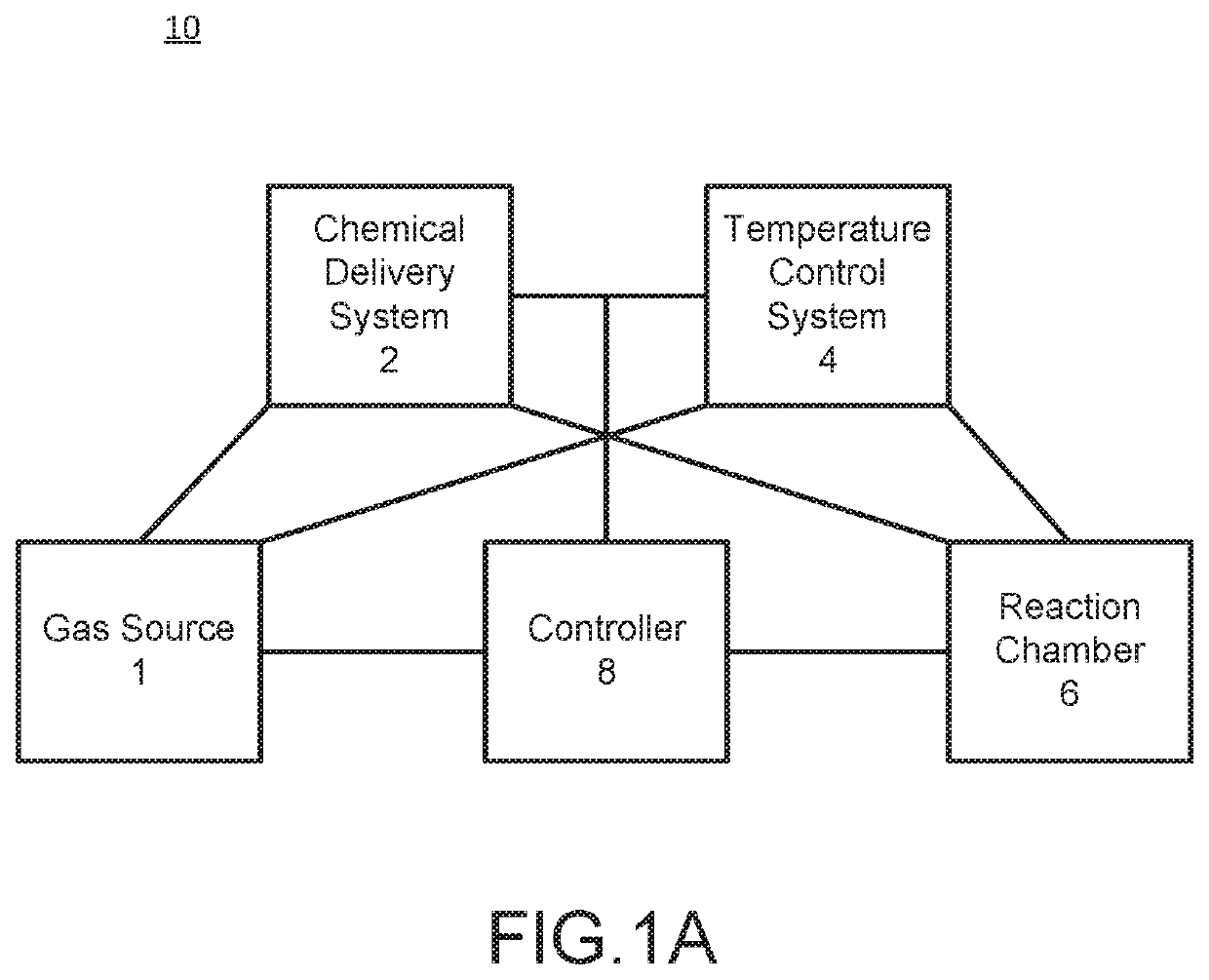
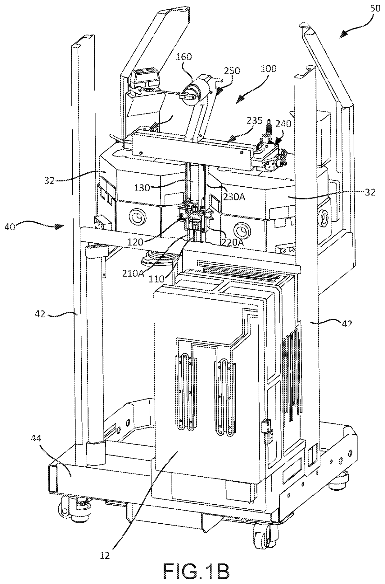
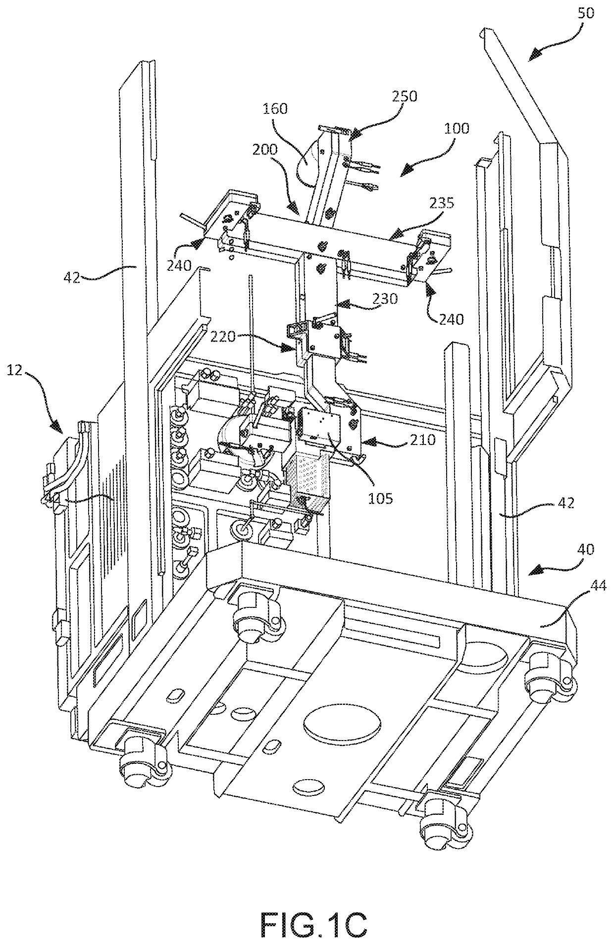
The present patent relates to temperature control systems for chemical delivery systems, particularly for use in reactor systems. The temperature control system may include heating or cooling shells that encapsulate various components of the chemical delivery system, such as the chemical delivery line, filter, accumulator, and application line. These shells may have temperature adjustment devices to control the temperature of the shells and the components they encapsulate. The temperature control system can maintain the temperature of the precursor or reactant gas at a target range to prevent degradation or condensation of the gas. The use of the temperature control system can improve the accuracy and stability of chemical delivery and reaction processes.

Problems solved by technology

Particularly when precursors or reactants are derived from liquid or solid sources, undesirable condensation can occur in a delivery path between a source and the reaction chamber.
However, if the precursors or reactants heated to a temperature that is too high, decomposition of the precursors or reactants occurs.

Method used


Image

  • Temperature-controlled chemical delivery system and reactor system including same
  • Temperature-controlled chemical delivery system and reactor system including same
  • Temperature-controlled chemical delivery system and reactor system including same

Examples


Embodiment Construction

[0021]The description of exemplary embodiments provided below is merely exemplary and is intended for purposes of illustration only. The following description is not intended to limit the scope of the disclosure or the claims. Moreover, recitation of multiple embodiments having stated features is not intended to exclude other embodiments having additional features or other embodiments incorporating different combinations of the stated features.

[0022]The present disclosure generally relates temperature-controlled chemical delivery systems, such as those comprised in a reactor system. The reactor system may be used to process substrates, such as semiconductor wafers, in gas-phase reactors. By way of examples, the systems described herein can be used to form or grow epitaxial layers (e.g., two component and / or doped semiconductor layers) on a surface of a substrate.

[0023]As used herein, a “substrate” refers to any material having a surface onto which material can be deposited. A substr...


PUM

PropertyMeasurementUnit
Temperatureaaaaaaaaaa
Flow rateaaaaaaaaaa

Abstract

A temperature control system for a chemical delivery system (e.g., comprised in a reactor system) may comprise a temperature control shell coupled to and / or enclosing at least a portion of at least one component of the chemical delivery system. A chemical delivery system may comprise a filter, an accumulator, and / or a chemical application line fluidly coupled to one another in any suitable arrangement and / or configuration. A temperature control system for such a chemical delivery system may comprise a filter temperature control shell coupled to and / or enclosing at least a portion of the filter, an accumulator temperature control shell coupled to and / or enclosing at least a portion of the accumulator, and / or an application line temperature control shell coupled to and / or enclosing at least a portion of the chemical application line.

Description

CROSS-REFERENCE TO RELATED APPLICATIONS[0001]This application is a nonprovisional of, and claims priority to and the benefit of, U.S. Provisional Patent Application No. 62 / 884,944, filed August 9, 2019 and entitled “TEMPERATURE-CONTROLLED CHEMICAL DELIVERY SYSTEM AND REACTOR SYSTEM INCLUDING SAME,” which is hereby incorporated by reference herein.FIELD OF DISCLOSURE[0002]The present disclosure generally relates to gas-phase reactors and systems. More particularly, the disclosure relates to temperature-controlled chemical delivery systems, to reactor systems including temperature-controlled chemical delivery systems, and to methods of using the same.BACKGROUND OF THE DISCLOSURE[0003]Gas-phase reactors, such as those use for chemical vapor deposition (CVD), plasma-enhanced CVD (PECVD), atomic layer deposition (ALD), and the like, can be used for a variety of applications, including depositing and etching materials on a substrate surface. For example, gas-phase reactors can be used to ...

Claims


Application Information

Patent Timeline
IPC IPC(8): C23C16/455C23C16/52H01L21/67
CPCC23C16/45561H01L21/67248C23C16/52C23C16/455H01L21/67017C30B25/14C30B25/165C23C16/448C23C16/4412
Inventor WHITE, CARL LOUISFONDURULIA, KYLESULLIVAN, TIMOTHY JAMES
Owner ASM IP HLDG BV
Learn More