
Application execution control system

a control system and application technology, applied in the field of application execution control system, can solve the problems of significant increase in the burden on the application side, and achieve the effect of reducing the burden on the application and the number of development steps, and reducing the variation in quality

Active Publication Date: 2021-02-11
FANUC LTD
View PDF0 Cites 0 Cited by
  • Summary
  • Abstract
  • Description
  • Claims
  • Application Information

AI Technical Summary

Benefits of technology

The patent text describes a system for controlling the execution of applications. The system monitors the design of the application and only provides instructions to the controller, reducing the burden on the application and simplifying the development process. The system also allows for standardized designs, removing any quality variations. Overall, the system improves efficiency and quality control during application development.

Problems solved by technology

However, in order to continue to cooperate with the CNC, the application needs to continue to periodically acquire and analyze the state and the information of the CNC, and thus a burden on the application side is significantly increased.

Method used


Image

  • Application execution control system
  • Application execution control system
  • Application execution control system

Examples


example 1

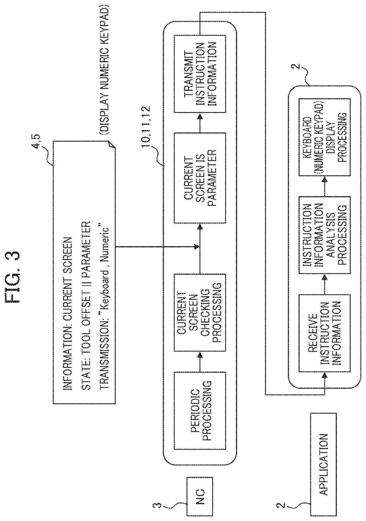
[0032]Here, when as shown in FIG. 3 (5), a current screen indicating the information and the state of the CNC 3 is a screen of a tool offset and a parameter, a numeric keypad is displayed on the screen, and the definition file 4 is defined such that the instruction information in the display of the numeric keypad is transmitted.

[0033]In the CNC 3, current screen checking processing is performed which checks the current screen with periodic processing that periodically performs the condition determination from various types of information of the CNC 3.

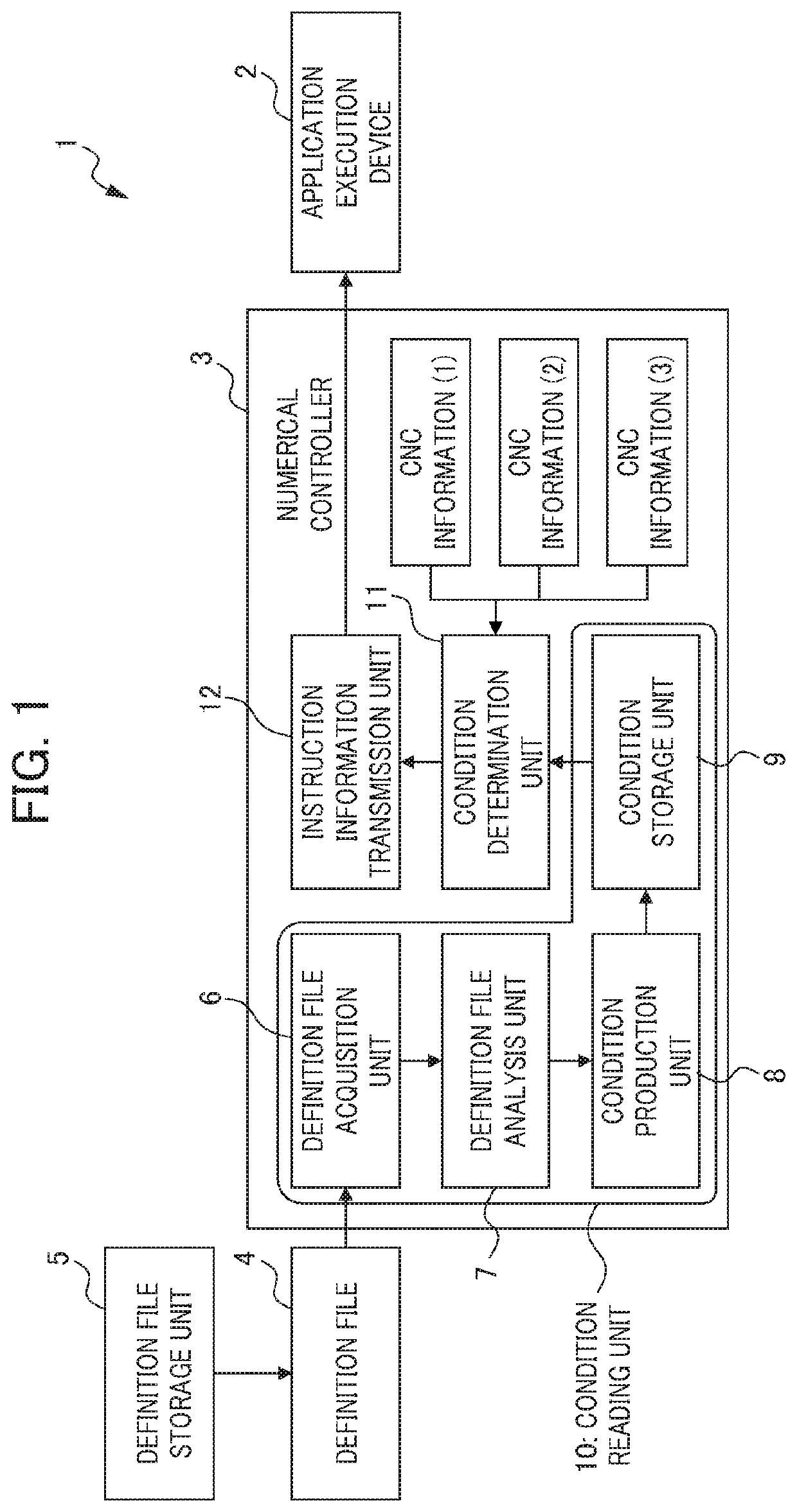
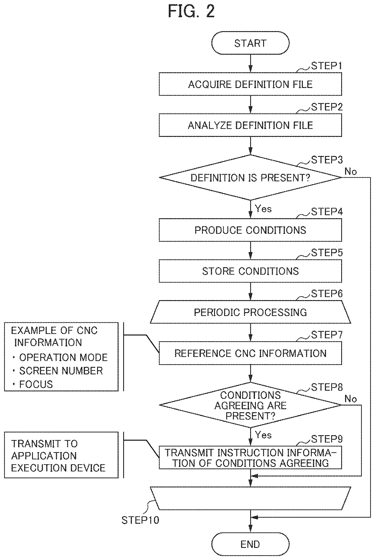
[0034]Specifically, in the periodic processing and the current screen checking processing, as shown in FIGS. 2 and 3 (5), the definition file acquisition unit 6 first acquires the definition file 4, and the definition file analysis unit 7 analyzes the acquired definition file 4 so as to check whether or not the definition is present (steps 2 and 3).

[0035]When the definition is not present, the transmission of the operation instruction i...

example 2

[0041]An example where when an alarm is generated, the information of the generated alarm is searched with a manual for will then be described.

[0042]When as shown in FIG. 4 (5), the current screen showing the information and the state of the CNC 3 is a screen of a tool offset, and a parameter, the definition file 4 is defined such that the instruction information of a manual display and the information of an alarm No. are transmitted.

[0043]In the CNC 3, alarm checking processing is performed which checks the alarm with the periodic processing that periodically performs the condition determination from various types of information of the CNC 3.

[0044]In the periodic processing and the alarm checking processing, as shown in FIGS. 2 and 4 (5), the definition file 4 is acquired, the acquired definition file 4 is analyzed and whether or not the definition is present is checked (steps 2 and 3).

[0045]When the definition is not present, the transmission of the operation instruction informati...


PUM


Abstract

An object is to provide an application execution control system which can reduce a burden on an application and the number of development steps. An application execution control system includes: a definition file storage unit which stores a definition file that defines instruction information which is transmitted according to the information and the state of a controller; a definition file acquisition unit; a definition file analysis unit which analyzes the acquired definition file; a condition production unit which produces, based on the result of the analysis, a determination condition of the information and the state of the controller; a condition storage unit which stores the produced determination condition; a condition determination unit which performs a condition determination from various types of information of the controller based on the determination condition; and an instruction information transmission unit which transmits the instruction information defined with the definition file when the condition determination is performed and the information of the controller agrees with the determination condition, and the application execution device executes processing with the instruction information transmitted from the instruction information transmission unit.

Description

[0001]This application is based on and claims the benefit of priority from Japanese Patent Application No. 2019-143558, filed on 5 Aug. 2019, the content of which is incorporated herein by reference.BACKGROUND OF THE INVENTIONField of the Invention[0002]The present invention relates to an application execution control system.Related Art[0003]As is known, for example, in the field of machine work, CNC (computer numerical controller: Computerized Numerical Control) technology is applied, the amount of movement of a tool, the speed of the movement thereof and the like are numerically controlled with a computer, and thus the repetition of the same machining procedure, the machining of a complicated shape and the like are highly automated (see, for example, patent documents 1 and 2).[0004]On the other hand, for example, in a case where a CNC is used to control the drive of an industrial machine, when an application designer wants to make a produced application and the CNC cooperate with ...

Claims


Application Information

Patent Timeline
Patent Type & Authority Applications(United States)
IPC IPC(8): G05B19/408G06F16/17G06F9/54G06F9/44
CPCG05B19/408G06F9/44G06F9/54G06F16/17G05B19/4155G05B2219/32026G06F11/3055G06F2201/865
Inventor JOUNISHI, RIKAMATSUKAWA, TOSHINORI
Owner FANUC LTD
Learn More