Inductor

a technology of inductance and inductance, which is applied in the direction of inductance, transformer/inductance details, inductance with magnetic core, etc., can solve the problems of deterioration of the insulation property of the coil, and achieve the effect of sufficient pressure resistance and high yield

Inactive Publication Date: 2021-02-11
MURATA MFG CO LTD
View PDF4 Cites 1 Cited by
  • Summary
  • Abstract
  • Description
  • Claims
  • Application Information

AI Technical Summary

Benefits of technology

[0005]Thus, the present disclosure provides an inductor manufacturable at a high yield, and having sufficient pressure resistance.

Problems solved by technology

However, when the mixture of the magnetic powder and the resin is disposed around the coil and compressed, particles of the magnetic powder enter a coating layer of a conductor of the coil, and an insulation property of the coil may be deteriorated.

Method used


Image

  • Inductor
  • Inductor
  • Inductor

Examples


example

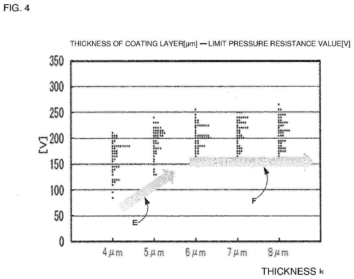
[0060]Next, with reference to FIG. 4, a working example will be described in which the inductor according to the embodiment is manufactured and tested. FIG. 4 is a graph illustrating the working example of the present disclosure, and is a graph showing a relationship between thickness and limit pressure resistance value (dielectric strength voltage) of a coating layer. A horizontal axis in FIG. 4 represents the thickness (μm) of the coating layer of the manufactured inductor, and a vertical axis represents the limit pressure resistance value (V) that is a test result of the manufactured inductor.

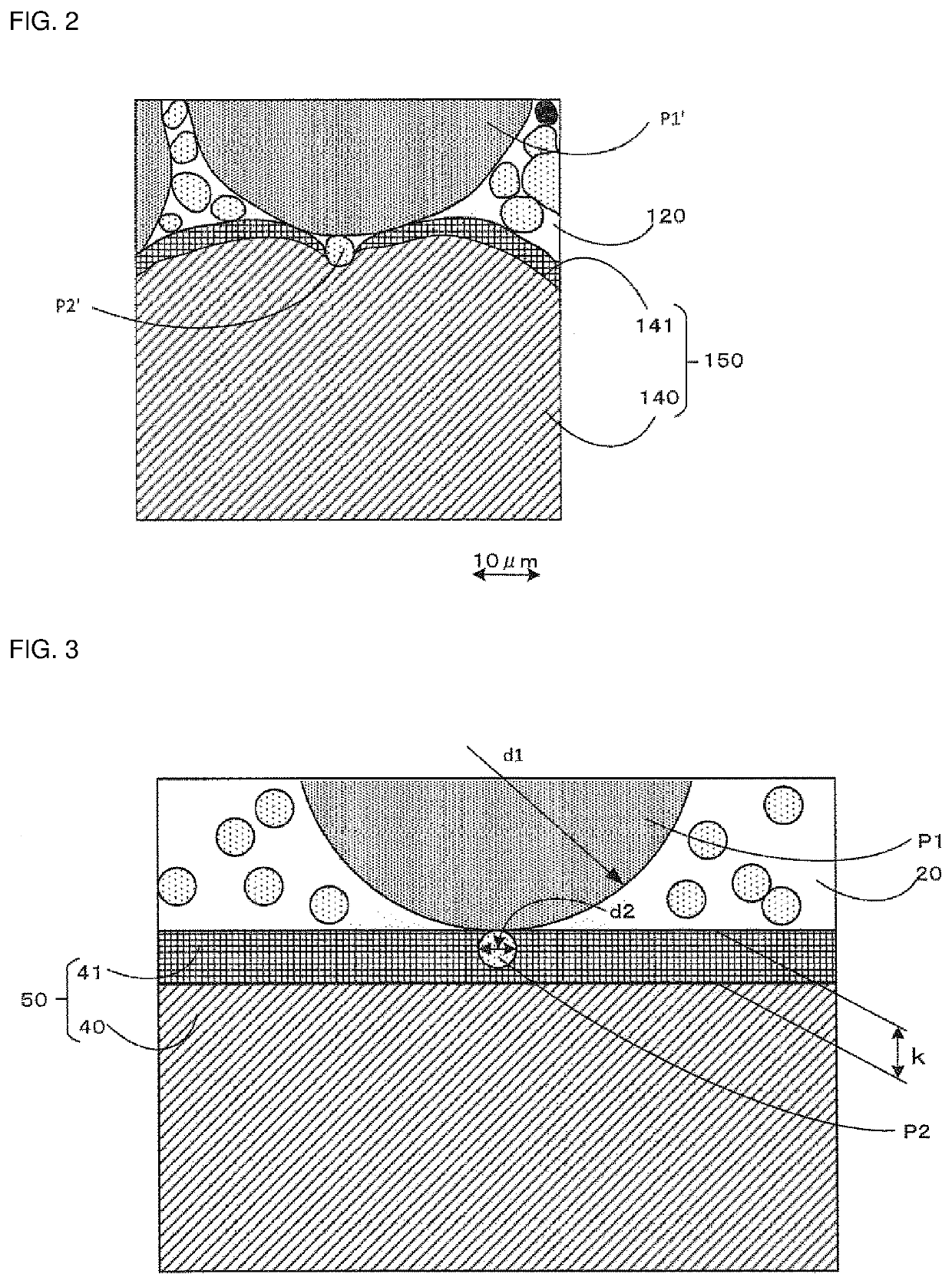
[0061]In the present working example, as the first particles P1 forming a magnetic portion, particles having the first average particle diameter d1 of about 50 μm were used, and as the second particles P2, particles having the second average particle diameter d2 of about 5 μm were used. In addition, inductors were manufactured by using rectangular wires having the thickness k of the coating ...


PUM

PropertyMeasurementUnit
particle diameteraaaaaaaaaa
heightaaaaaaaaaa

Abstract

An inductor that includes a coil having a winding portion in which a conductor having a coating layer is wound, and a pair of lead-out portions formed by leading out the conductor from the winding portion; and a magnetic portion including magnetic powder and resin and configured to seal the coil. The magnetic powder includes first particles having a first average particle diameter, and second particles having a second average particle diameter smaller than the first average particle diameter, and a thickness of the coating layer has a value larger than the second average particle diameter.

Description

CROSS-REFERENCE TO RELATED APPLICATION[0001]This application claims benefit of priority to Japanese Patent Application No. 2019-146155, filed Aug. 8, 2019, the entire content of which is incorporated herein by reference.BACKGROUNDTechnical Field[0002]The present disclosure relates to an inductor having a coil, and a magnetic portion for sealing the coil.Background Art[0003]An inductor having a coil and a magnetic portion for sealing the coil has been widely used. There has been proposed a method of manufacturing an inductor in which a mixture of magnetic powder and resin is disposed around a coil, compressed, and subjected to pressure bonding to form a magnetic portion that seals the coil, as described, for example, in Japanese Unexamined Patent Application Publication No. 2009-246398.[0004]However, when the mixture of the magnetic powder and the resin is disposed around the coil and compressed, particles of the magnetic powder enter a coating layer of a conductor of the coil, and a...

Claims


Application Information

Patent Timeline
Patent Type & Authority Applications(United States)
IPC IPC(8): H01F27/28H01F27/255H01F41/061H01F41/02
CPCH01F27/2823H01F41/0246H01F41/061H01F27/255H01F17/04H01F27/2847H01F27/2852H01F2017/048
Inventor MIZUKOSHI, YASUTAKAOHAGA, TAKEOKITAJIMA, MASAKI
Owner MURATA MFG CO LTD
Why Eureka
Try Eureka