Electrical module junction box transfer device (e-jbtd) system having electrical energy internal and external connections

a transfer device and electrical energy technology, applied in the direction of photovoltaics, electrical apparatus, multi-connection sub-assemblies, etc., can solve the problems of inability to install an electrical energy junction box (j-box) device, affecting the aesthetics and imperfections, and affecting the installation. , to achieve the effect of safe securing and easy non-impinging wiring configuration

Pending Publication Date: 2021-02-11
SOLARWINDOW TECH
View PDF4 Cites 1 Cited by
  • Summary
  • Abstract
  • Description
  • Claims
  • Application Information

AI Technical Summary

Benefits of technology

[0003]The present invention recognizes that the discrete points of contact or connection in conventional electrical wiring connection systems present challenges for the installation of electricity-generating glass (EGP) devices that have limited or constrained access by space or location. The present invention also recognizes that current mounting systems present a challenge in safely securing electricity-generating glass (EGP) devices to vertical surface of structures, while at the same time allowing for easy non-impinged wiring configurations.

Problems solved by technology

In the conventional art, the installation of an electrical energy junction box (J-Box) device may be compromised or prohibited by difficult, if not impossible, installations due to space, fixture, building and mounting unit constraints that do not allow proper or secure electrical connection.
The conventional art is also mounted to the back of drilled glass, which provides weak and possible points of fracture, locations for moisture ingress causing failed electrical connections or electrical shorts, and flawed aesthetics and imperfections.

Method used


Image

  • Electrical module junction box transfer device (e-jbtd) system having electrical energy internal and external connections
  • Electrical module junction box transfer device (e-jbtd) system having electrical energy internal and external connections
  • Electrical module junction box transfer device (e-jbtd) system having electrical energy internal and external connections

Examples


Embodiment Construction

[0024]The present invention now is described more fully hereinafter with reference to the accompanying drawings, in which embodiments of the invention are shown. This invention, however, may be embodied in many different forms and should not be construed as limited to the embodiments set forth herein; rather, these embodiments are provided so that this disclosure will be thorough and complete, and will fully convey the scope of the invention to those skilled in the art.

[0025]Referring now to the drawings, exemplary embodiments of an Electrical Module Junction Box Transfer Device (E-JBTD).

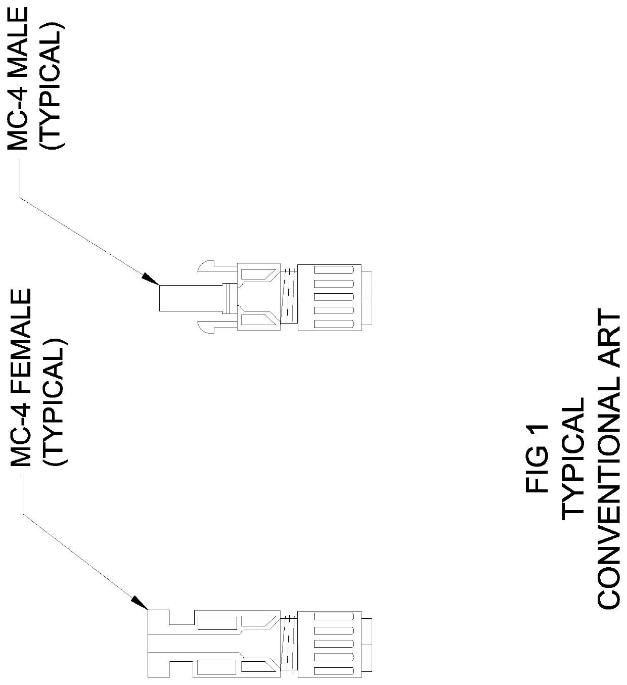
[0026]FIG. 1 illustrates an example of a conventional MC-4 connector that is configured to fasten and connect an electricity-generating glass (EGP) device outside rated insulated conductor to a module or other device.

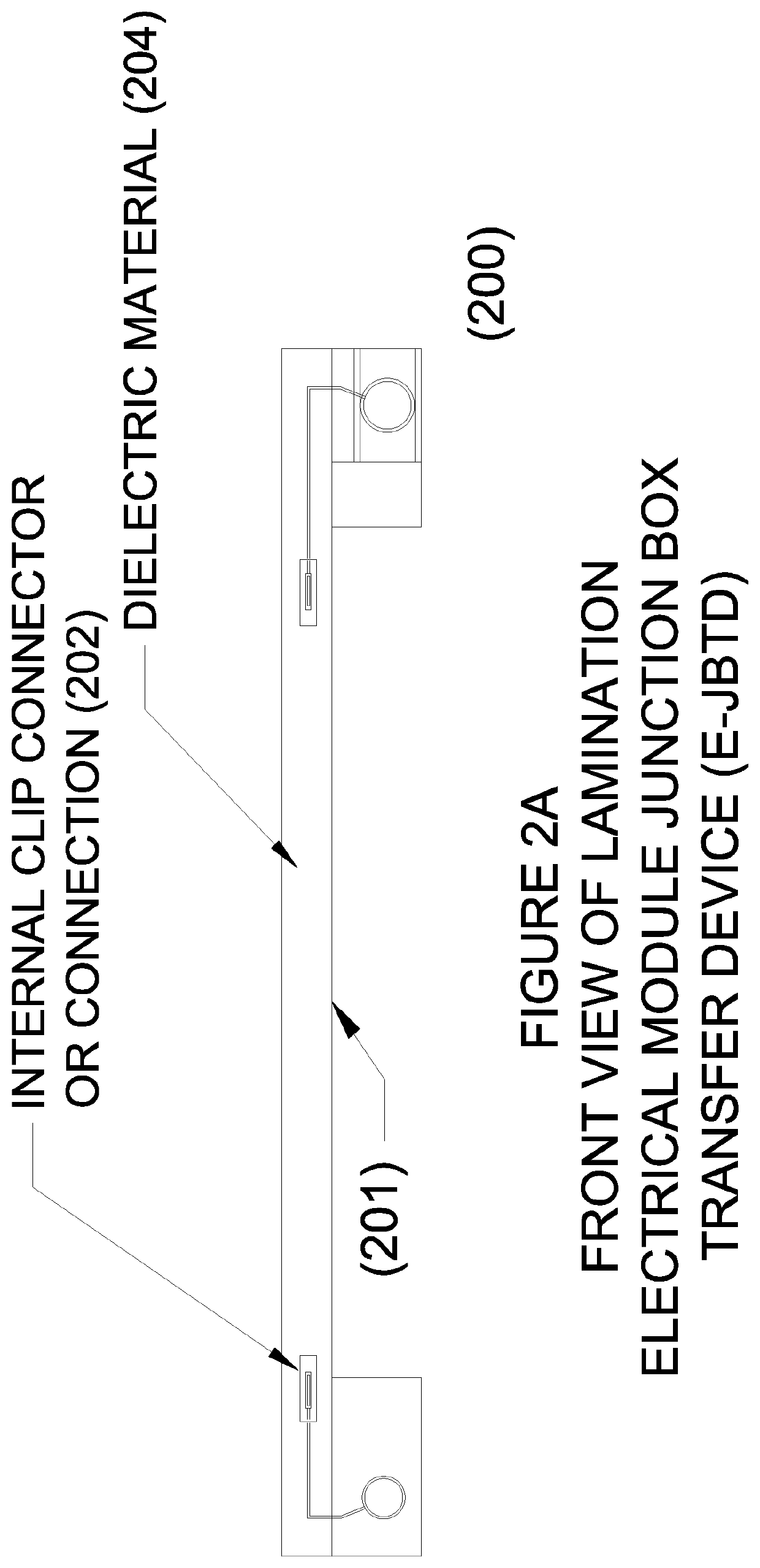
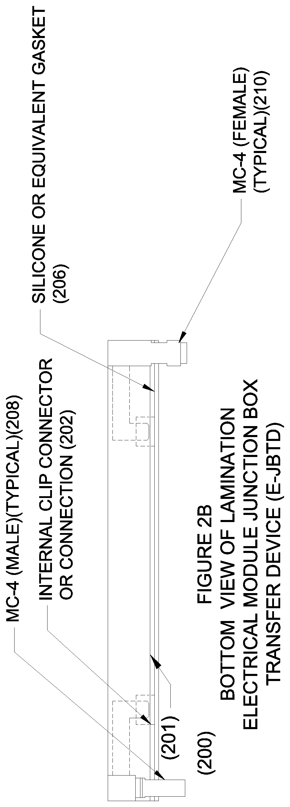
[0027]FIGS. 2A-4B illustrate exemplary embodiments of an Electrical Module Junction Box Transfer Device (E-JBTD) 200 according to the invention.

[0028]Particularly, FIGS. 2A-2C illustrat...


PUM

PropertyMeasurementUnit
non-conductive dielectricaaaaaaaaaa
non-conductiveaaaaaaaaaa
insulatingaaaaaaaaaa

Abstract

An Electrical Module Junction Box Transfer Device (E-JBTD) includes one or more electrical connectors, and a non-conductive dielectric insulating material protecting the one or more electrical connectors. A system includes an electricity-generating glass (EGP) device, and an Electrical Junction Box Electron Transfer Device (E-JBTD) on the electricity-generating glass (EGP) device. The Electrical Module Junction Box Transfer Device (E-JBTD) is water and weather tight, maintains a secure electrical connection between modules or electricity-generating glass (EGP) devices, and may not be removed after installation and reinstalled on another module or electricity-generating glass (EGP) device.

Description

CROSS-REFERENCE TO RELATED APPLICATIONS[0001]This application claims priority under 35 U.S.C. 119(e) of U.S. Provisional Application No. 62 / 854,276, filed on May 29, 2019, (Attorney Docket No. 7006 / 0189PR01), the entire contents of which are hereby incorporated by reference and for which priority is claimed under 35 U.S.C. § 120.BACKGROUND[0002]A conventional electrical wiring connection system may include a wiring system and components (electrical energy hardware, wire and terminal contacts, connections, etc.) to transfer electrical energy from a device (such as an electricity-generating glass or flexible substrate product(s) (EGPs)) to wires for use. These connections commonly must rely on electrical wiring connections, adding connectors, and installation of junction boxes at discrete points of contact or connection, and electrical testing.SUMMARY OF THE INVENTION[0003]The present invention recognizes that the discrete points of contact or connection in conventional electrical wir...

Claims


Application Information

Patent Timeline
Patent Type & Authority Applications(United States)
IPC IPC(8): H02G3/08H02S40/34H05K7/02
CPCH02G3/08H05K7/026H02S40/34Y02E10/50
Inventor CONKLIN, JOHN A.SARGENT, PATRICK T.
Owner SOLARWINDOW TECH
Why Eureka
Try Eureka