Base station apparatus, terminal apparatus, and communication method
- Summary
- Abstract
- Description
- Claims
- Application Information
AI Technical Summary
Benefits of technology
Problems solved by technology
Method used
Image
Examples
first embodiment
1. First Embodiment
[0029]The base station apparatus and the terminal apparatus in the present embodiment can communicate in a frequency band in which a license is required (licensed band) and / or a frequency hand in which a license is not required (unlicensed band).
[0030]According to the present embodiments, “X / Y” includes the meaning of “X or Y”. According to the present embodiments, “X / Y” includes the meaning of “X and Y”. According to the present embodiments, “X / Y” includes the meaning of “X and / or Y”.
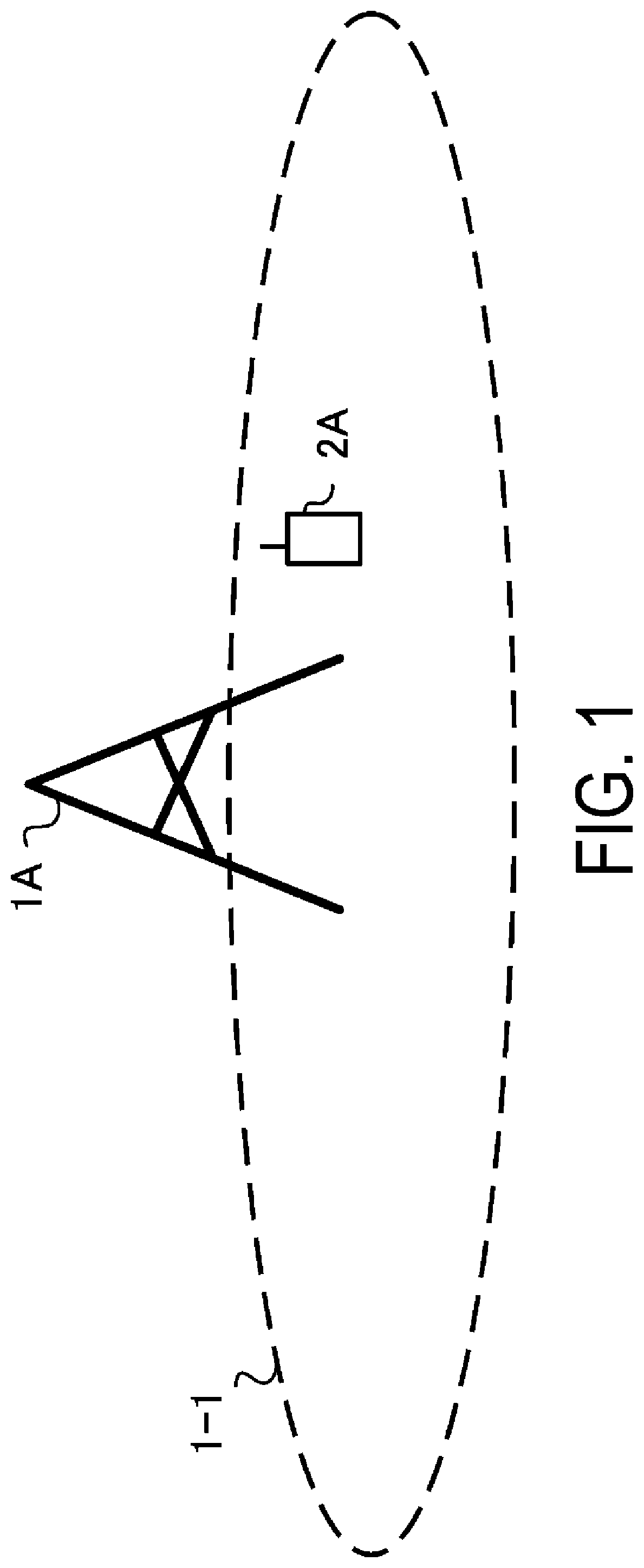
[0031]FIG. 1 is a diagram illustrating an example of a communication system according to the present embodiment. As illustrated in FIG. 1, the communication system according to the present embodiment includes a base station apparatus 1A and a terminal apparatus 2A. Coverage 1-1 is a range (a communication area) in which the base station apparatus 1A can connect to the terminal apparatus. Furthermore, the base station apparatus 1A is also simply referred to as a base station apparatus...
second embodiment
2. Second Embodiment
[0205]The communication apparatus (base station apparatus and terminal apparatus) according to the present embodiment can communicate in a frequency band in which a license is required (licensed band) and / or a frequency band in which a license is not required (unlicensed band). The receiver included in the communication apparatus according to the present embodiment includes a function of performing carrier sense, which will be described later.
[0206]The communication apparatus according to the present embodiment can reserve a radio medium particularly in the unlicensed hand by carrier sense (LBT). At this time, the communication apparatus has different lengths of the radio medium that can be reserved by the LBT (e.g., in a case that an idle state of the radio medium can be determined by the LBT, a period in which the communication apparatus can continuously transmit the frame in the radio medium), depending on parameters configured to the LBT to be performed. Spec...
third embodiment
3. Third Embodiment
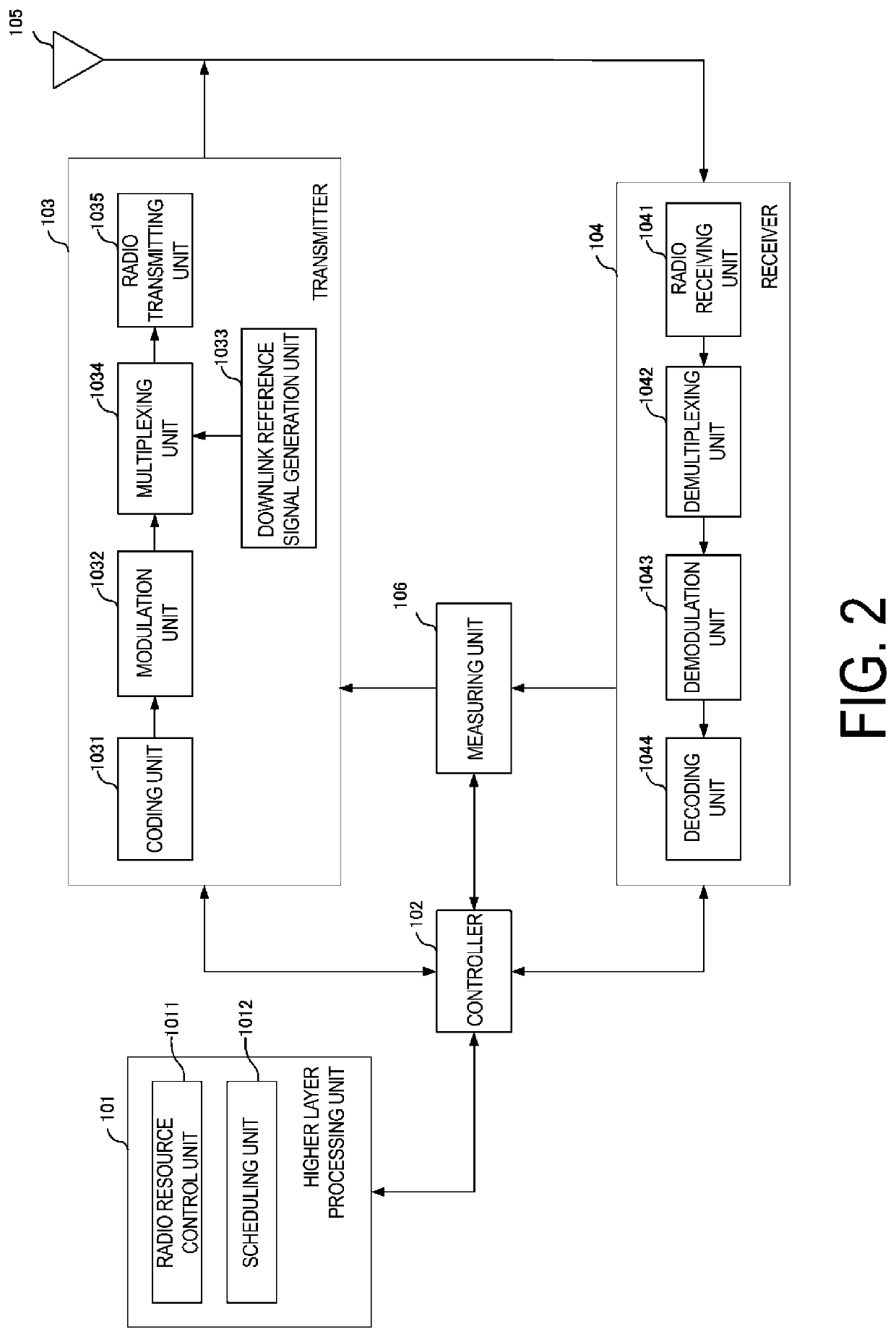
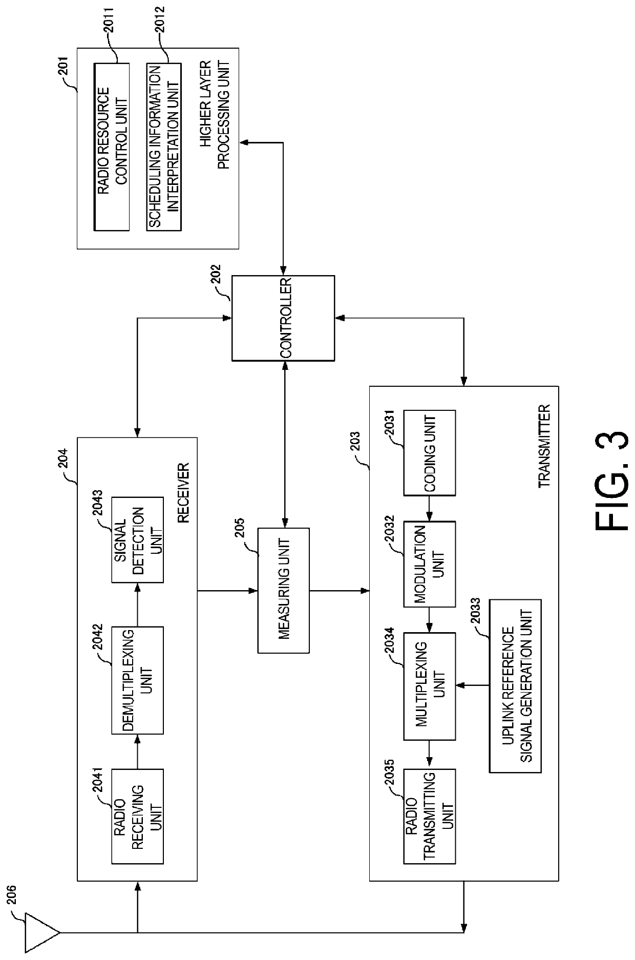
[0211]The communication apparatus (base station apparatus and terminal apparatus) according to the present embodiment Obtains information related to a base station apparatus density in the periphery or information related to the number of beam candidates used by base station apparatuses in the periphery by exchanging the information among the communication apparatuses (base station apparatuses). For the configuration of the base station apparatus, the configuration in which an inter-base station interface unit 107 is added to the configuration illustrated in FIG. 2 is used. FIG. 6 illustrates an example of the configuration of this base station apparatus. For the configuration of the terminal apparatus, the configuration illustrated in FIG. 3 is used.
[0212]The inter-base station interface unit 107 is an interface unit for exchanging information with other base station apparatuses without passing through the higher layer processing unit 101, and the connection sche...
PUM
 Abstract
Description
Claims
Application Information
 - R&D
- Intellectual Property
- Life Sciences
- Materials
- Tech Scout
- Unparalleled Data Quality
- Higher Quality Content
- 60% Fewer Hallucinations
Browse by: Latest US Patents, China's latest patents, Technical Efficacy Thesaurus, Application Domain, Technology Topic, Popular Technical Reports.
© 2025 PatSnap. All rights reserved.Legal|Privacy policy|Modern Slavery Act Transparency Statement|Sitemap|About US| Contact US: help@patsnap.com


