
Surface-mounted silicone lens

Inactive Publication Date: 2021-02-18
CORELED SYST
View PDF0 Cites 1 Cited by
  • Summary
  • Abstract
  • Description
  • Claims
  • Application Information

AI Technical Summary

Benefits of technology

The patent describes a way to put silicone optics on a printed circuit board with other electronic parts. This makes it easier and faster to make certain devices.

Problems solved by technology

Surface-mount technology has been generally limited to installation of electronic devices onto a printed circuit board, with non-electronic, functional components being added in separate steps using different technology.

Method used


Image

  • Surface-mounted silicone lens

Examples


Embodiment Construction

[0011]Described herein are optical components that are mountable to a printed circuit board (PCB) using surface-mount technology in which solder reflow is used to permanently secure the optical component to the PCB. The optical components are supported by or integrated onto a surface mount device having a dielectric body and a solderable support connected with the dielectric body. As used herein, the term “optical component” includes lens, reflectors, filters, and polarizers.

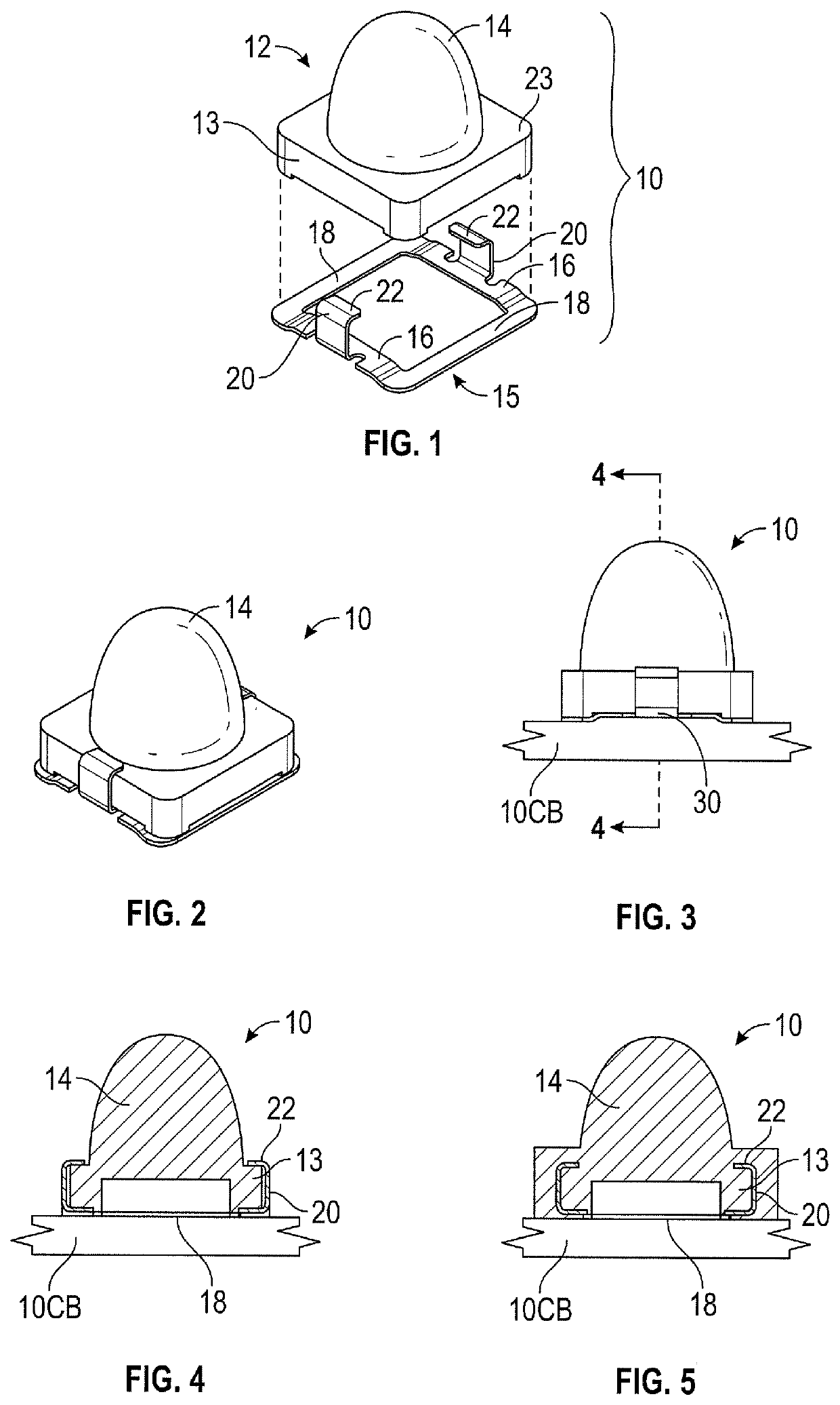
[0012]A surface-mount device 10 having a silicone optic or lens member 12 having a lens portion 14 and a base portion 13 is attached to a lead frame clip 15 as shown in FIG. 1. Lens member 12 and lead frame clip 15 are configured to be reversibly or releasably connected together into a snap-fit assembly. As an alternative, the lead frame clip could be insert molded or overmolded with the dielectric body.

[0013]The lead frame 15 can be made of various solderable materials. Suitable solderable metal and metal oxide...


PUM


Abstract

An optical surface-mount device has a silicone lens member and a solderable support connected with the silicone lens member to facilitate solder reflow mounting of the device to a printed circuit board.

Description

CROSS-REFERENCE TO RELATED APPLICATIONS[0001]This application is a Continuation-in-Part of U.S. application Ser. No. 16 / 539,399 filed Aug. 13, 2019, and which is incorporated herein by reference in its entirety.FIELD OF THE DISCLOSURE[0002]This disclosure relates to surface-mount devices and improvements in surface-mount technology.BACKGROUND OF THE DISCLOSURE[0003]Surface-mount technology has been generally limited to installation of electronic devices onto a printed circuit board, with non-electronic, functional components being added in separate steps using different technology.[0004]U.S. Pat. No. 8,585,242 describes a securement ring adapted to hold a lens and which is surface mountable to a printed circuit board.SUMMARY OF THE DISCLOSURE[0005]This disclosure provides methods of using surface-mount technology to install silicone optics on a printed circuit board. The method can allow silicone optics to be installed on a printed circuit board simultaneously with electronic compon...

Claims


Application Information

Patent Timeline
IPC IPC(8): G02B7/02H05K1/18
CPCG02B7/02H05K2201/10393H05K2201/10121H05K1/181G02B7/022H01L25/0753H01L33/486H01L33/58H01L33/62H05K3/301H05K2201/10106H05K2201/10606
Inventor WELLS, BRIAN C.MALLORY, DEREKKAHL, JOHNSTADTHERR, DIANNAGODWIN, STEPHENSALTON, ROBERT
Owner CORELED SYST
Learn More