Multi-Modal Imaging System and Method for Non-Invasive Examination of an Object to be Examined

a multi-modal imaging and object technology, applied in the field of multi-modal imaging system and method for non-invasive examination of an object to be examined, can solve the problems of low image recording rate and slow reaction time of motor-driven optical units

Pending Publication Date: 2021-02-25
JENLAB
View PDF0 Cites 1 Cited by
  • Summary
  • Abstract
  • Description
  • Claims
  • Application Information

AI Technical Summary

Benefits of technology

[0009]Below, “multi-modal” is understood to mean that two, three or four systems are provided, which are at least partly integrated in one another. The systems can share individual components with one another, for example if one or more measuring or imaging systems use the same radiation source, transmission optical unit, focusing optical unit or the same detector system. Advantageously, a compact arrangement is proposed, in which individual components can be used simultaneously or successively by a plurality of systems. By way of example, the systems can facilitate different imaging modes in succession or at the same time.
[0089]According to an advantageous embodiment, the excitation beam is released if the examination object is present in the measurement region. By way of example, this can ensure patient safety.

Problems solved by technology

A disadvantage of this lies in the slow reaction time of the motor-driven optical unit and, as a consequence thereof, a low image recording rate.

Method used


Image

  • Multi-Modal Imaging System and Method for Non-Invasive Examination of an Object to be Examined
  • Multi-Modal Imaging System and Method for Non-Invasive Examination of an Object to be Examined
  • Multi-Modal Imaging System and Method for Non-Invasive Examination of an Object to be Examined

Examples


Embodiment Construction

[0108]The exemplary embodiments described below with reference to figures should not be construed as restricting the subject matter of the invention. The figures represent the subject matter of the invention only schematically.

[0109]In the figures, the same or similar components have been provided with the same reference sign, with repeat mention of these components being dispensed with in the description in individual cases.

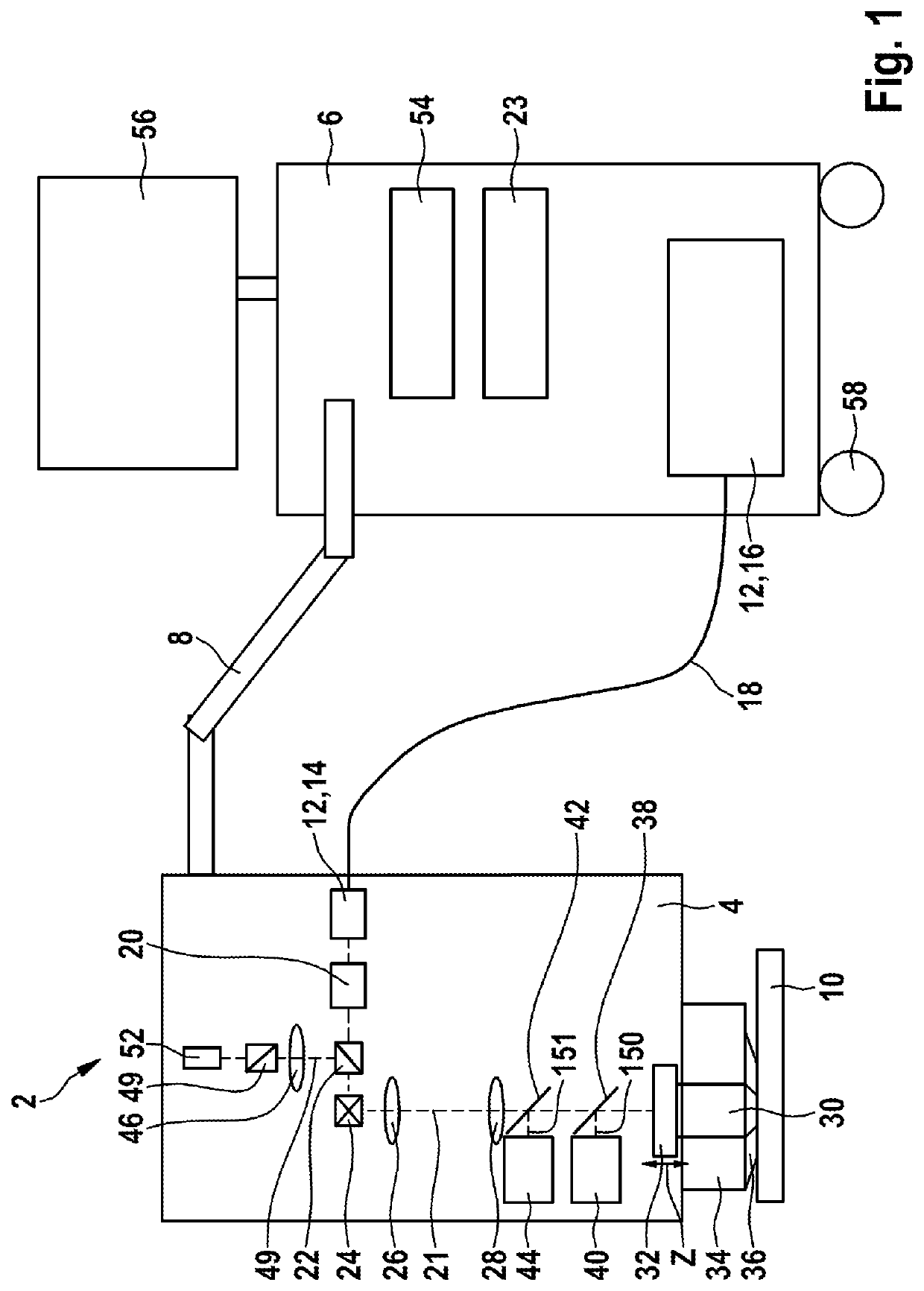
[0110]FIG. 1 shows a schematic illustration of a multi-modal imaging system 2 as per a first embodiment of the invention.

[0111]The multi-modal imaging system 2 comprises a measuring head 4 which is pivotable, rotatable and flexibly positionable freely in space such that an examination of an examination object 10 is performable under any desired solid angle.

[0112]For the purposes of positioning the measuring head 4 freely, the latter is fastened to a mobile base device 6 by means of an articulated arm 8.

[0113]The multi-modal imaging system 2 comprises a radiation...


PUM

PropertyMeasurementUnit
lengthsaaaaaaaaaa
diameteraaaaaaaaaa
diameteraaaaaaaaaa

Abstract

The invention relates to a multi-modal imaging system (2) for non-invasive examination of an examination object (10), comprising a multi-photon imaging system for providing high-resolution detailed images of the examination object (10), which imaging system comprises a radiation source (12), the latter generating an excitation beam (21) of near infrared femtosecond laser radiation for triggering secondary radiation emitted by the examination object (10), and a focusing optical unit (30), by means of which the radiation of the radiation source (12) is directable at a measurement position of the examination object (10), wherein the focusing optical unit (30) and a laser head (14) of the radiation source (12) are provided in a measuring head (4), which is pivotable, rotatable and flexibly positionable freely in space such that the examination of the examination object (10) is performable under any desired solid angle, and comprising at least one confocal detection device, which is at least partly integrated in the measuring head (4) as well and which is configured to receive a signal of the excitation beam (21) of near infrared femtosecond laser radiation, which was diffusely reflected by the examination object (10).Moreover, a method is specified for non-invasive examination of an examination object (10) using a multi-modal imaging system (2), as is the use of the multi-modal imaging system (2) for examining living matter of the examination object (10)

Description

[0001]The invention relates to a multi-modal imaging system and to a method for non-invasive examination of an examination object.PRIOR ART[0002]U.S. Pat. No. 5,034,613 A, DE 20 117 294 U1, DE 20 306 122 U1, and DE 10 2010 047 578 A1 disclose rigid and flexible systems for multi-photon imaging using pulsed laser radiation in the near infrared range. By way of example, high-resolution microscopic image fields with edge lengths in the region significantly below 1 mm are generated using multi-photon imaging.[0003]DE 10 2009 029 831 A1 proposes the use of so-called flying optics, wherein an optical unit for focusing excitation radiation and for exciting secondary radiation is not arranged in stationary fashion but moved overall in order to excite, successively in time, different locations of an object to be examined. Here, the spatial excitation is implemented not by beam deflection using rotation and tilt mirrors but by a one-dimensional or multi-dimensional movement of the optical uni...

Claims


Application Information

Patent Timeline
Patent Type & Authority Applications(United States)
IPC IPC(8): A61B5/00
CPCA61B5/0035A61B5/0037A61B5/0066A61B2562/0247A61B5/0077A61B5/444A61B5/6843A61B5/0071G01N21/6458G02B21/0028G02B21/0076A61B5/748
Inventor KÖNIG, KARSTENWEINIGEL, MARTIN
Owner JENLAB
Why Eureka
Try Eureka