Battery system for an electric vehicle, method for operating a battery system, and electric vehicle

a battery system and electric vehicle technology, applied in the direction of battery/fuel cell control arrangement, battery/electric vehicle, instruments, etc., can solve the problems of high cost and disadvantage of battery system space and weight, redundancy in control unit, and inability to operate the battery system. to achieve the effect of minimizing costs, space and weight of the battery system, high fault tolerance and high safety level

Active Publication Date: 2021-02-25
ROBERT BOSCH GMBH
View PDF0 Cites 0 Cited by
  • Summary
  • Abstract
  • Description
  • Claims
  • Application Information

AI Technical Summary

Benefits of technology

This patent describes a battery system for electric vehicles that has a high tolerance for faults. The system uses multiple sensors to monitor the battery cells and electronic components. If there is a deviation in the measured values, it is considered a potential defect. The system also has a mechanism to distinguish between defects in the battery cells, modules, or in the sensor system / electronic system. This allows for early diagnosis and treatment of defects, which prevents malfunctions in the battery system that could cause damage to the vehicle. The use of standard hardware and a software extension makes the monitoring system cost-effective and safer. The patent also describes how the battery system can continue to operate even if there is a defect in the sensor system / electronic system.

Problems solved by technology

Autonomously operated electric vehicles are subject to special requirements, in particular concerning roadworthiness, since a breakdown of such electric vehicles is particularly problematic.
If the control unit (BCU) or one of the supervision units (CSC) fails in a simple battery system, the battery system can no longer be operated and the electric vehicle breaks down.
Such a duplication entails high costs and disadvantages with respect to space and weight of the battery system.
There is thus a redundancy in the control unit.

Method used


Image

  • Battery system for an electric vehicle, method for operating a battery system, and electric vehicle
  • Battery system for an electric vehicle, method for operating a battery system, and electric vehicle

Examples


Embodiment Construction

[0040]Identical or similar elements are designated by the same reference numerals in the following description of the specific embodiments of the present invention, a repeated description of these elements being omitted in individual cases. The figures represent the subject matter of the present invention only schematically.

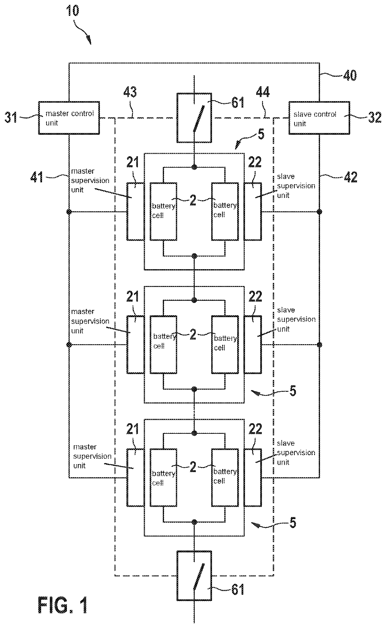
[0041]FIG. 1 shows a schematic representation of a battery system 10 for an electric vehicle. Battery system 10 comprises a plurality of battery modules 5, which are interconnected in series. Each of the battery modules 5 has multiple, presently two, battery cells 2 interconnected in parallel. Said battery cells 2 are lithium-ion battery cells for example.

[0042]Battery system 10 further comprises a master control unit 31 for supervising battery modules 5 and a slave control unit 32 for supervising battery modules 5. A master supervision unit 21 having master sensors (not shown here) is assigned to each of the battery modules 5. Likewise, a slave supervision unit ...


PUM

PropertyMeasurementUnit
voltagesaaaaaaaaaa
temperaturesaaaaaaaaaa
weightaaaaaaaaaa

Abstract

A battery system for an electric vehicle. The electric vehicle includes a plurality of serially interconnected battery modules, each battery module having at least two battery cells interconnected in parallel, a master control unit for supervising the battery modules, and a slave control unit for supervising the battery modules. A master supervision unit having master sensors for detecting measured values of the battery cells and of the battery module and a slave supervision unit having slave sensors for detecting measured values of the battery cells and of the battery module are assigned to each battery module. The master supervision units communicate with the master control unit, the slave supervision units communicate with the slave control unit, and the master control unit communicates with the slave control unit.

Description

CROSS REFERENCE[0001]The present application claims the benefit under 35 U.S.C. § 119 of German Patent Application No. DE 102019212479.8 filed on Aug. 21, 2019, which is expressly incorporated herein by reference in its entirety.FIELD[0002]The present invention relates to a battery system for an electric vehicle, which comprises a plurality of serially interconnected battery modules, each battery module having at least two battery cells interconnected in parallel, a master control unit for supervising the battery modules, and a slave control unit for supervising the battery modules. The present invention further relates to a method for operating a battery system in accordance with the present invention. The present invention furthermore relates to an electric vehicle.BACKGROUND INFORMATION[0003]Today's electrically driven vehicles, which are called electric vehicles, provide battery systems having multiple battery cells. The battery cells are interconnected not only serially, but al...

Claims


Application Information

Patent Timeline
Patent Type & Authority Applications(United States)
IPC IPC(8): B60L3/00H01M10/48B60L58/12B60L58/22G01R31/396
CPCB60L3/0046H01M10/482H01M2010/4278B60L58/22G01R31/396B60L58/12G01R31/392G01R31/371G01R35/00H01M2220/20H01M50/509Y02T90/16H01M2220/30
Inventor SCHMIDT, ALEXANDERWOLL, CHRISTOPH
Owner ROBERT BOSCH GMBH
Why Eureka
Try Eureka