

Three-phase synchronous rectifier for battery charger on board vehicle
a battery charger and synchronous rectifier technology, which is applied in the direction of voltage/current isolation, instruments, transportation and packaging, etc., can solve the problems of difficult to measure the voltage drop, the inability to use conventional automotive-type generators, and the difficulty of power dissipation in aluminum finned enclosures with reduced overall dimensions
- Summary
- Abstract
- Description
- Claims
- Application Information
AI Technical Summary
Benefits of technology
Problems solved by technology
Method used
Image

Examples
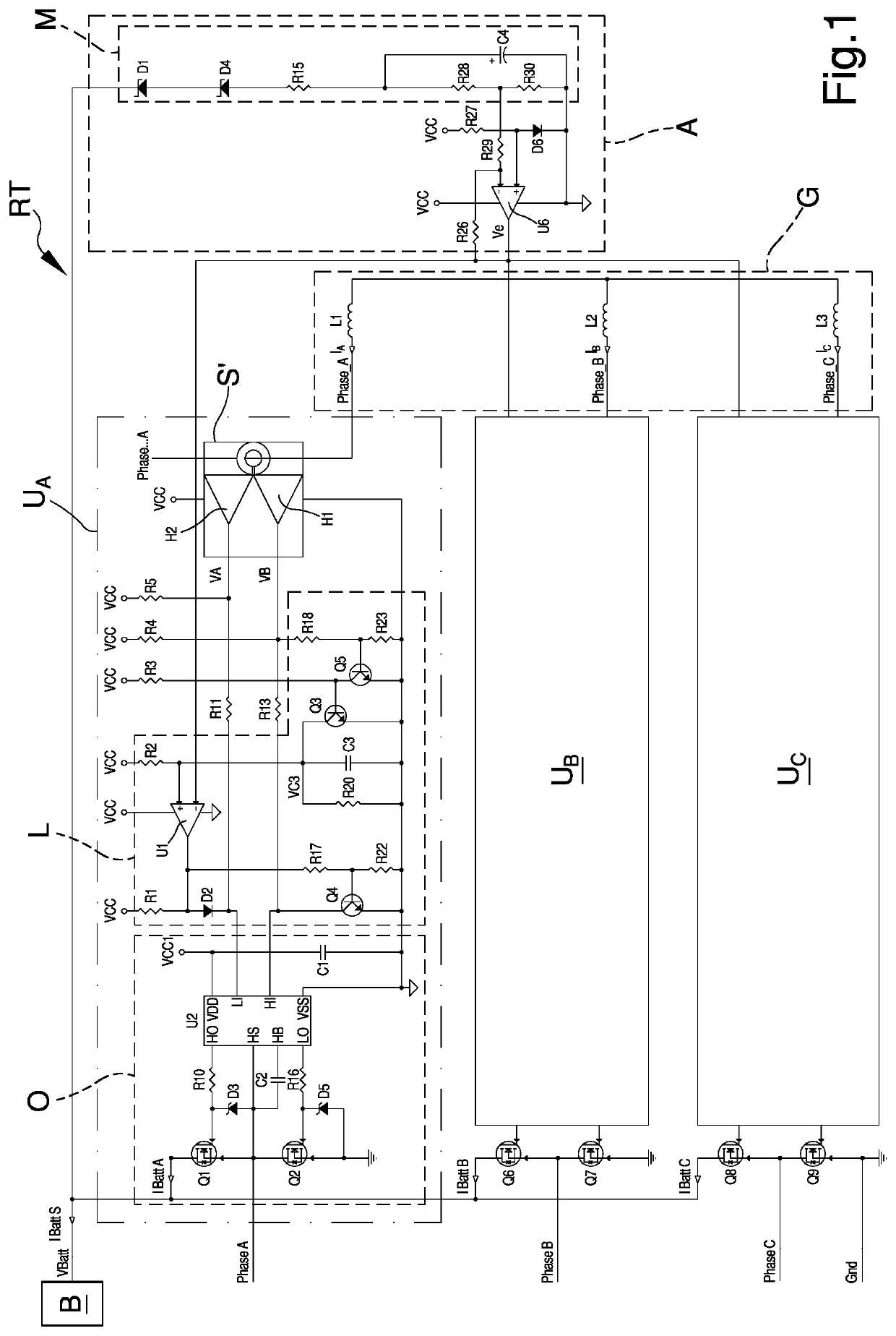
first embodiment
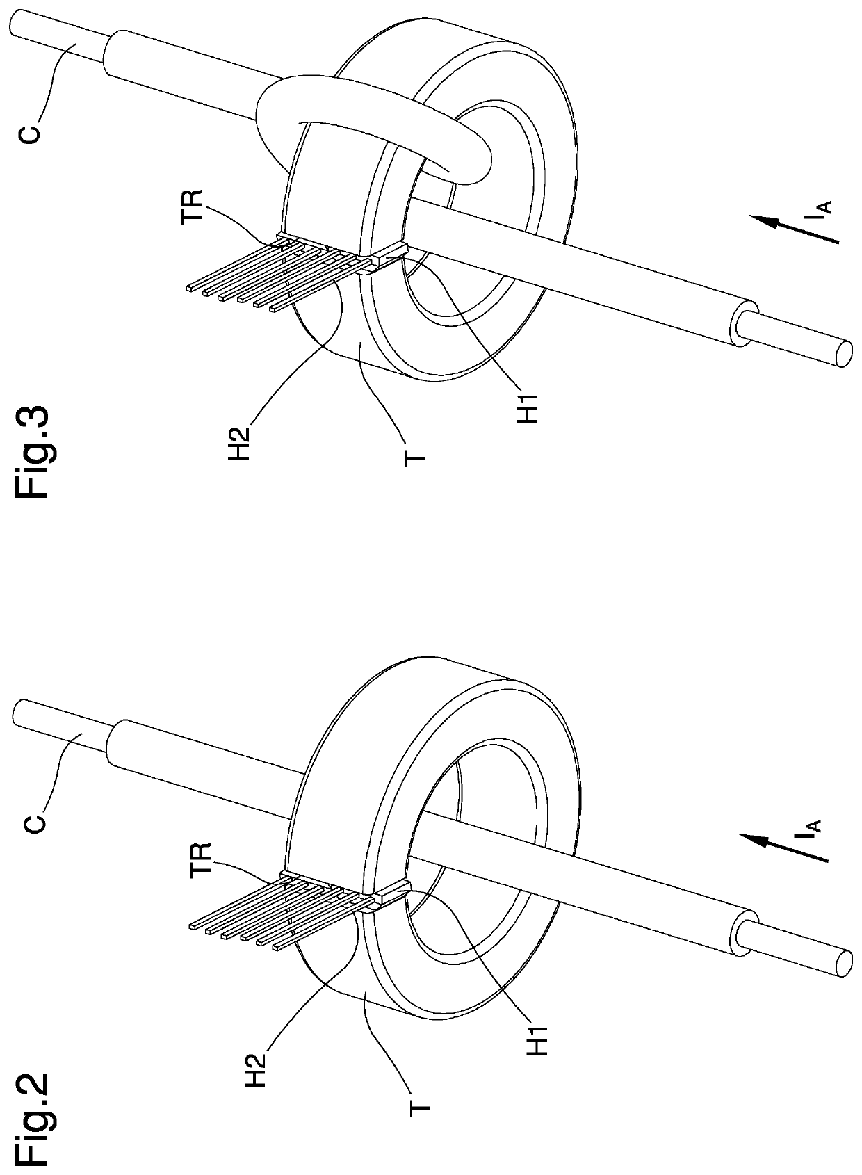
[0019]FIGS. 2 and 3 illustrate different possible implementations of a current sensor that can be used in the three-phase synchronous rectifier according to the invention;
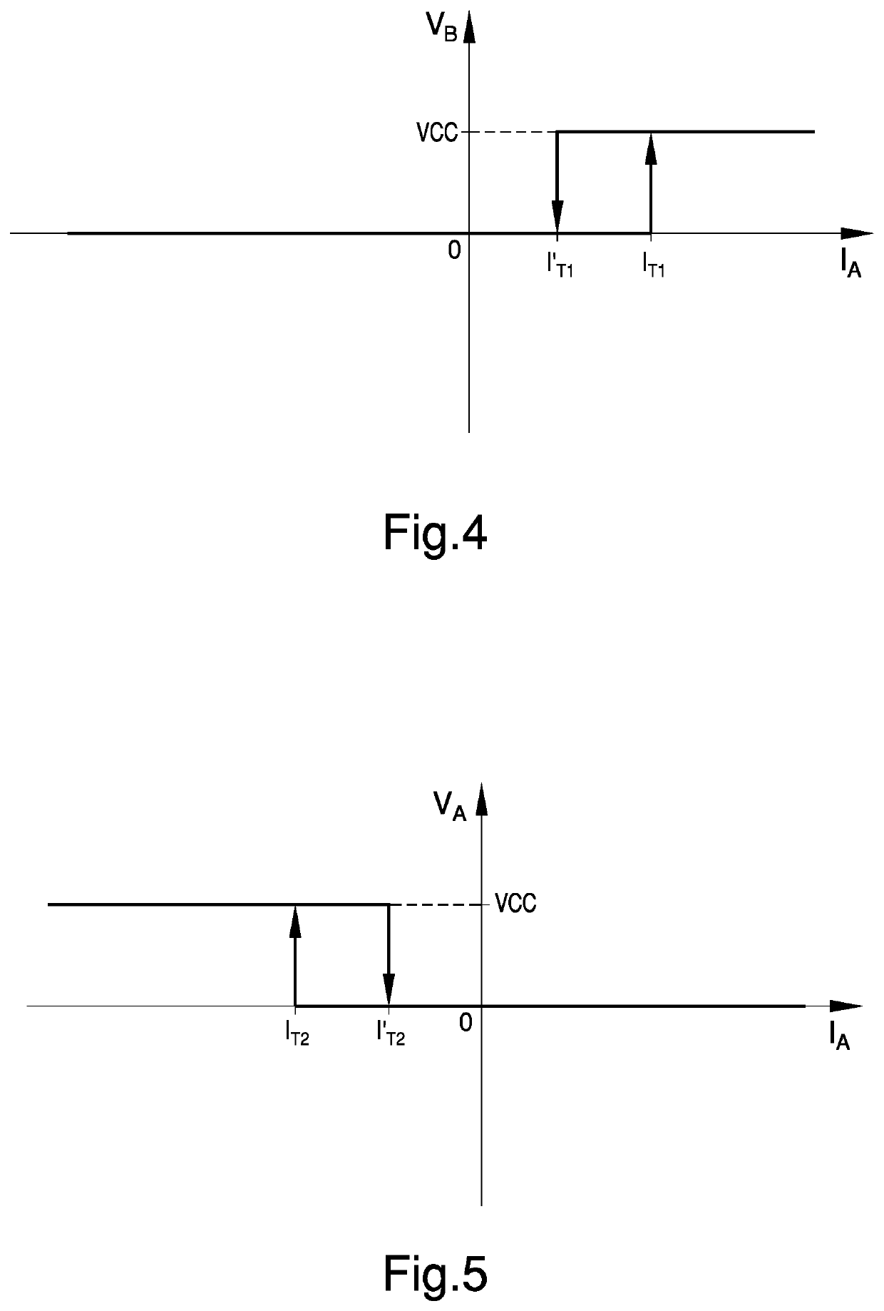
[0020]FIG. 4 is a graph illustrating the pattern of the output signal of a first Hall sensor according to the first embodiment of the three-phase synchronous rectifier;
[0021]FIG. 5 is a graph illustrating the pattern of the output signal of a second Hall sensor according to the first embodiment of the three-phase synchronous rectifier;
[0022]FIG. 6 graphically illustrates the patterns of the signals with reference to the first embodiment of the three-phase synchronous rectifier according to the invention;
[0023]FIG. 7 is a general electrical diagram illustrating a second possible embodiment of the three-phase synchronous rectifier according to the invention;
second embodiment
[0024]FIGS. 8 and 9 illustrate different possible implementations of a current sensor that can be used in the three-phase synchronous rectifier according to the invention;
[0025]FIG. 10 graphically illustrates the patterns of the signals with reference to the second embodiment of the three-phase synchronous rectifier according to the invention.
PUM
 Abstract
Description
Claims
Application Information