
Channelised gain control of line amplifiers

a gain control and channelised technology, applied in line-transmission details, repeater circuits, waveguides, etc., can solve the problems of human error in gain setting, significant drawbacks of both methods, and decrease in the intensity of rf signal within the leaky coaxial cable, so as to facilitate the adjustment of gain control

Active Publication Date: 2021-02-25
RF IND
View PDF5 Cites 0 Cited by
  • Summary
  • Abstract
  • Description
  • Claims
  • Application Information

AI Technical Summary

Benefits of technology

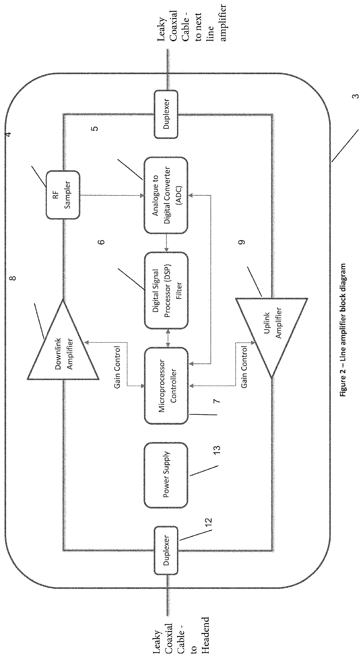
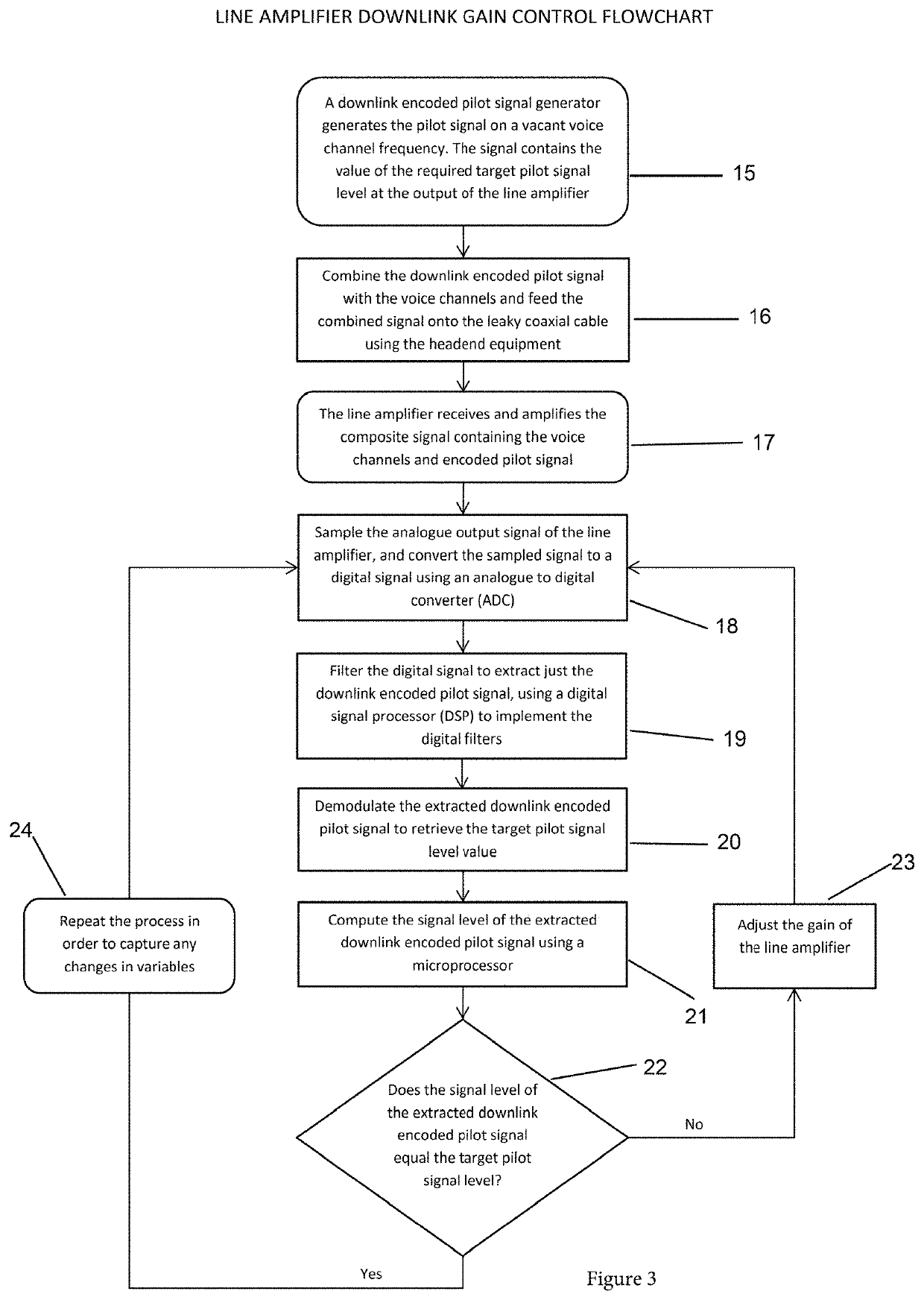
The present invention provides a system for controlling the gain of a line amplifier on a cable to adjust the signal strength of a pilot signal. The pilot signal is fed into the cable as a pulsed signal on an unused channel frequency. The system uses a controller to determine the pilot signal output strength, compare it with a target signal strength, and adjust the gain control of the amplifier accordingly. This allows for automatic adjustment of the gain control in response to changes in the pilot signal. The system can be used in a cable television network to control the signal strength of the pilot signal to ensure proper operation of the line amplifier.

Problems solved by technology

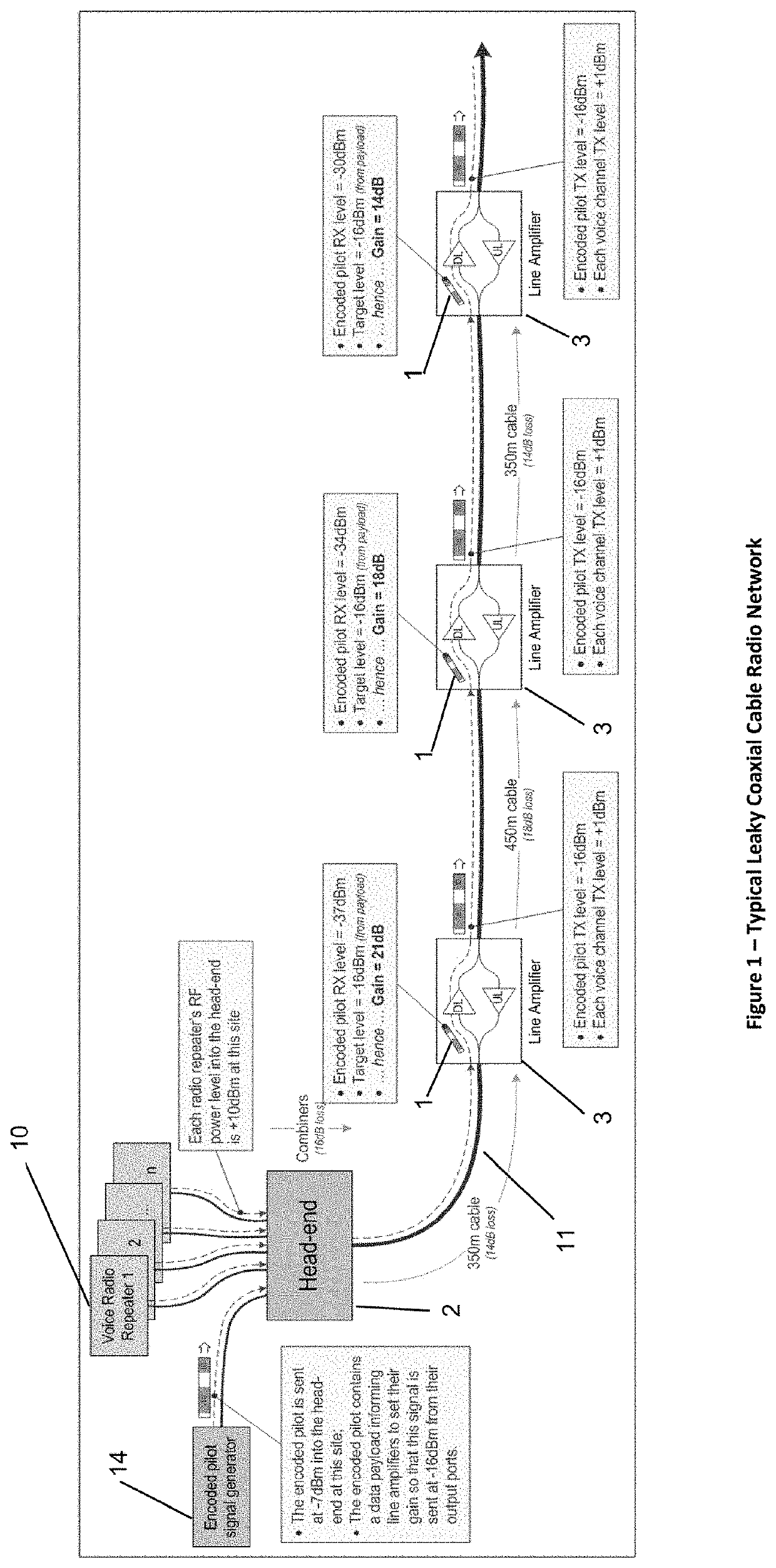
A limitation of leaky cables is that the RF signal intensity within the leaky coaxial cable decreases as it travels away from the feed point at the base station repeater.
This is due to transmission and cable losses.
This can be quite a challenge since tunnel networks can be extremely long (up to 100 km in some cases), and hence will comprise hundreds of cascaded line amplifiers.
Both methods have significant drawbacks, which are described below.
The gain setting is subject to human error, particularly in underground mining deployments where technicians are not equipped with advanced test equipment due to the nature of the environment;
The individual line amplifiers are typically installed high up the tunnel walls or on the tunnel roof, meaning that access to them is extremely difficult.
As a result, the gain adjustments are often overlooked, leading to a degradation and possible failure of the radio network with major health and safety consequences.
Whilst this approach overcomes the disadvantages of manual gain control, it has its own disadvantages:
The gain is compromised when more voice channels are present due to the increased composite output power, meaning that the range of the radio network is compromised compared to what it would be if say a single voice channel was active;

Method used


Image

  • Channelised gain control of line amplifiers
  • Channelised gain control of line amplifiers
  • Channelised gain control of line amplifiers

Examples


Embodiment Construction

[0063]The following description is presented to enable any person skilled in the art to make and use the invention, and is provided in the context of a particular application and its requirements. Various modifications to the disclosed embodiments will be readily apparent to those skilled in the art, and the general principles defined herein may be applied to other embodiments and applications without departing from the spirit and scope of the present invention. Thus, the present invention is not intended to be limited to the embodiments shown, but is to be accorded the widest scope consistent with the principles and features disclosed herein.

[0064]The invention describes a novel approach to achieving line amplifier gain control without the disadvantages of both manual and traditional automatic gain control techniques. The following description refers to improvements to a typical leaky coaxial cable radio network deployment as depicted in FIG. 1.

[0065]In a preferred embodiment, a lo...


PUM


Abstract

A method for controlling gain of a line amplifier on a cable, the method comprising selecting an unused carrier frequency; transmitting a pulsed pilot signal on the unused carrier frequency into the cable; determining a pilot signal output strength by measuring signal strength of the pilot signal after amplification by the line amplifier; comparing the pilot signal output strength with a target signal strength to determine a difference; and adjusting the gain of the line amplifier corresponding to the difference.

Description

[0001]This nonprovisional application claims priority under 35 U.S.C. § 119(a) to Australian Patent Application No. 2019903091, which was filed in Australia on Aug. 23, 2019, and which is herein incorporated by reference.FIELD OF THE INVENTION[0002]The present invention relates to line amplifiers and in particular to line amplifiers on leaky feeders such as those used in mines and tunnels.BACKGROUND TO THE INVENTION[0003]Voice communications between workers deployed in tunnel-type environments, such as for example, underground mines, or tunnels being constructed for new transport infrastructure, are typically enabled by narrowband duplex radio networks, using either analogue or digital modulation schemes. These radio networks may typically operate in either the UHF or VHF spectrum bands; VHF being the most prevalent.[0004]The radio communication transmissions (RF) are typically conveyed via a “leaky” coaxial cable or leaky feeder. That is, a coaxial cable with discontinuities in its...

Claims


Application Information

Patent Timeline
Patent Type & Authority Applications(United States)
IPC IPC(8): H03G3/00H01Q13/20H01P3/06
CPCH03G3/005H01P3/06H01Q13/203H04B1/04H04B2001/0416H03G3/20H04B3/36H03F2201/3206H01B11/18H04B3/10H03G3/3036
Inventor SNELL, CHRISTOPHER JOHNPOPE, GREGORY STEVEN
Owner RF IND
Learn More