Laser Sintering 3D Printing Thermal Compensation System and Method

Inactive Publication Date: 2021-03-04
AIC RD TECH CO LTD
View PDF0 Cites 4 Cited by
  • Summary
  • Abstract
  • Description
  • Claims
  • Application Information

AI Technical Summary

Benefits of technology

[0014]c) sintered bed thermal compensation step: heating the part of the surface powder layer not covering the sintered bed by a heating device for thermal compensation, thereby making the temperature field temperature of the surface powder layer more evenly.
[0015]The present invention reduces the temperature difference between the high temperature re

Problems solved by technology

Due to the uneven temperature field temperature of powder layers during the operation of con

Method used


Image

  • Laser Sintering 3D Printing Thermal Compensation System and Method
  • Laser Sintering 3D Printing Thermal Compensation System and Method
  • Laser Sintering 3D Printing Thermal Compensation System and Method

Examples


Embodiment Construction

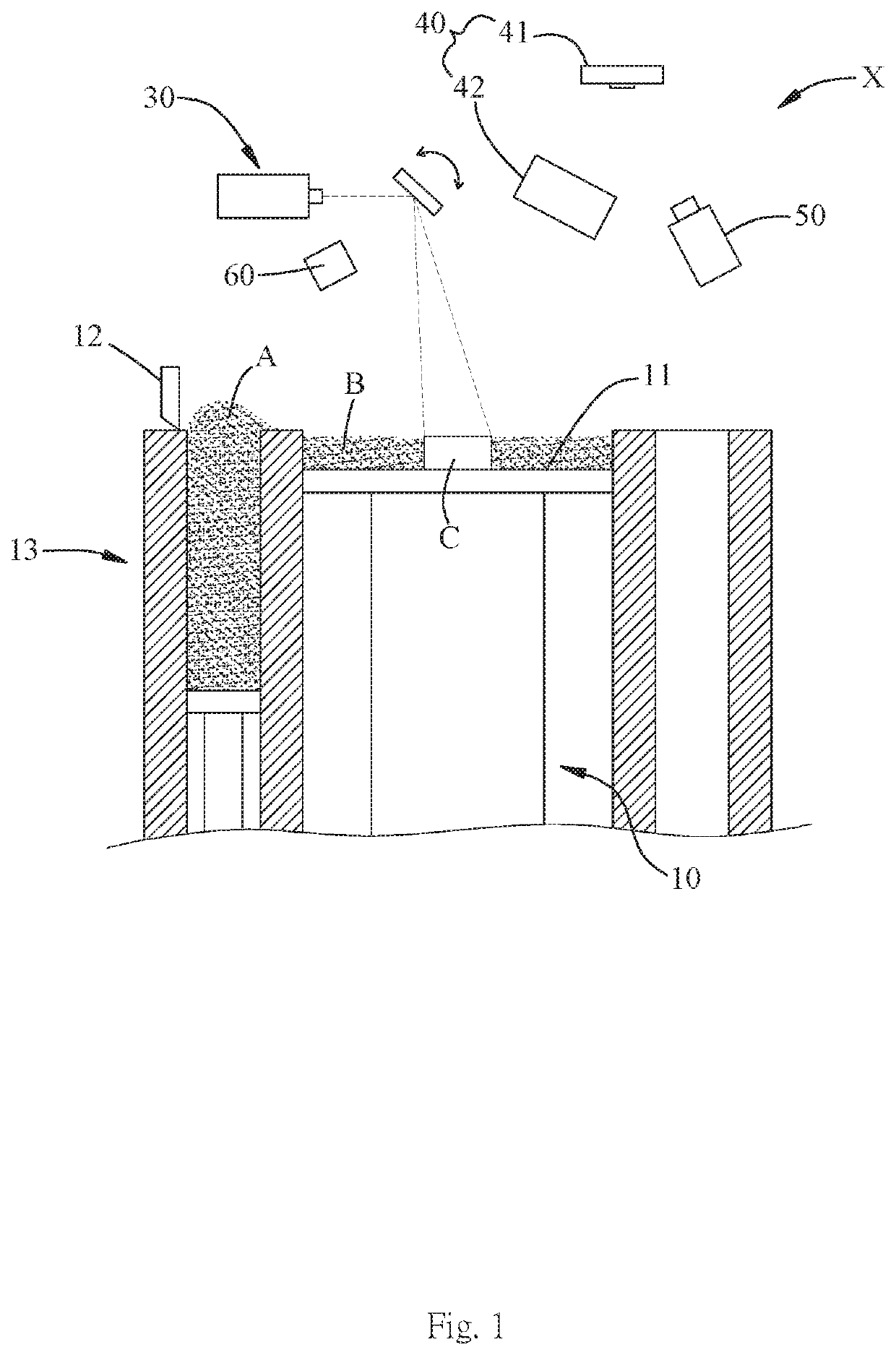
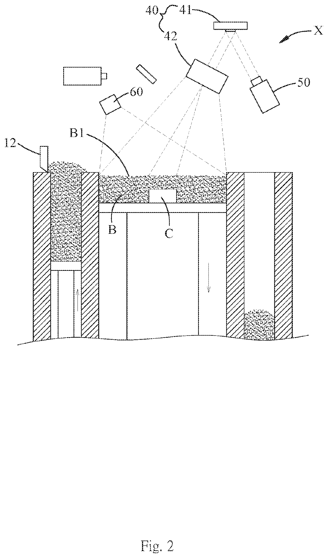
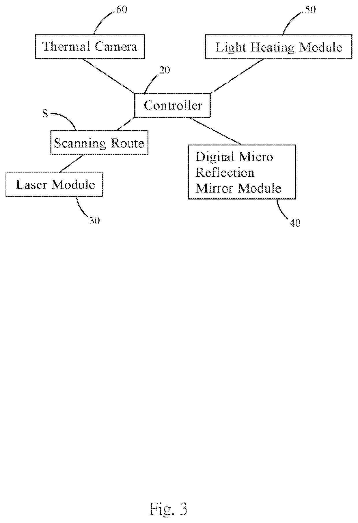
[0023]Reference will now be made in detail to the present preferred embodiments of the invention, examples of which are illustrated in the accompanying drawings. Wherever possible, the same reference numbers are used in the drawings and the description to refer to the same or like parts. It is not intended to limit the method or the system by the exemplary embodiments described herein. In the following detailed description, for purposes of explanation, numerous specific details are set forth in order to attain a thorough understanding of the disclosed embodiments. It will be apparent, however, that one or more embodiments may be practiced without these specific details. As used in the description herein and throughout the claims that follow, the meaning of “a”, “an”, and “the” includes reference to the plural unless the context clearly dictates otherwise. Also, as used in the description herein and throughout the claims that follow, the terms “comprise or comprising”, “include or in...


PUM

PropertyMeasurementUnit
Temperatureaaaaaaaaaa

Abstract

A laser sintering 3D printing thermal compensation system is provided and includes a controller and a heating device and a temperature field sensing device respectively connected to the controller, in which the temperature field sensing device is configured to determine a detection result by detecting within a printing region, the detection result includes a high temperature region and a relatively low-temperature region, and the controller is configured to control the heating device to heat the relatively low-temperature region for conducting thermal compensation, thereby reducing the temperature difference between the high temperature region and the relatively low-temperature region, and overcoming drawbacks of conventional arts having inaccurate control of the temperature field, causing interface defects due to temperature unevenness, and, consequently, greatly reducing the printing quality.

Description

FIELD OF THE INVENTION[0001]The present invention relates to a laser sintering 3D printing manner, and more particularly to a system and method for laser sintering 3D printing thermal compensation.BACKGROUND OF THE INVENTION[0002]Conventional Laser Sintering 3D printing (Selective Laser Sintering; SLS / Selective Laser Melting; SLM) is to respectively sinter and cure the uppermost metal or polymer powder layer layer-by-layer by high power lasers, so that the printed product can be gradually formed while repeatedly curing and sintering the powder layers. The unsintered powder of the powder layers play a role of supporting the printing of the intermediate product during the 3D printing process, and the unsintered portion can be finally removed while the printed product is formed and the printing process is completed.[0003]The aforementioned laser sintering 3D printing is conventionally performed by a few steps including selectively sintering a portion of a powder layer by a high power l...

Claims


Application Information

Patent Timeline
IPC IPC(8): B22F3/105B33Y10/00B33Y30/00B33Y50/02B29C64/153B29C64/268B29C64/277B29C64/393
CPCB22F3/1055B33Y10/00B33Y30/00B33Y50/02B22F2003/1057B29C64/268B29C64/277B29C64/393B29C64/153B22F12/10B22F12/90B22F2999/00B22F10/28B22F12/45Y02P10/25B22F12/44B22F10/368B22F10/00
Inventor JIAN, YI-MING
Owner AIC RD TECH CO LTD
Why Eureka
Try Eureka