Conveyor

Pending Publication Date: 2021-03-04
KONICA MINOLTA INC
View PDF1 Cites 3 Cited by
  • Summary
  • Abstract
  • Description
  • Claims
  • Application Information

AI Technical Summary

Benefits of technology

The invention aims to create a conveyor that can accurately detect the position of an ultrasonic sensor even in the face of external factors like noise caused by vibration and impact.

Problems solved by technology

While the housing or the frame maintains robustness, the reception element stably keeps the inclined posture, but when the housing or the frame comes to lose the robustness in a latter stage of durability, the reception element loses the stability and becomes gradually affected by vibration and impact from a roller or a guide plate existing in a periphery of the reception element.
A noise caused by the vibration spreads over a wide frequency band, and there may be a noise generated at a resonance frequency of the reception element.
The noise generated at such a resonance frequency cannot be removed by a bandpass filter or the like disclosed in a conventional technology.
As described above, the conventional technology does not have a technique to suppress the noise caused by decrease in the robustness of the housing or the frame due to approach to the latter stage of durability, and there is a problem that accuracy of the double feed determination is deteriorated in the latter stage of durability and various troubles relating to sheet conveyance may be caused.
As far as attenuation of ultrasonic waves at the time of sheet passage is utilized, the sheet type determination may also have a problem of the above-described determination accuracy in the latter stage of durability, and there is a problem that a manufacturer having developed a conveyor may be plagued by such accuracy deterioration in the double feed determination and the sheet type determination.
Even in a case of utilizing, for the double feed determination, an ultrasonic sensor (reflective ultrasonic sensor) in which a transmission element and a reception element are arranged on one side of a conveyance path and a reflected wave of an ultrasonic wave transmitted from the transmission element is received therein, there also is the problem of deterioration of determination accuracy as described above.

Method used


Image

  • Conveyor
  • Conveyor
  • Conveyor

Examples


first embodiment

[0042]Hereinafter, an embodiment of an image forming apparatus including a conveyor according to the present invention will be described by using a multi-function printer (MFP) as an example.

[1] External View of Image Forming Apparatus 1000

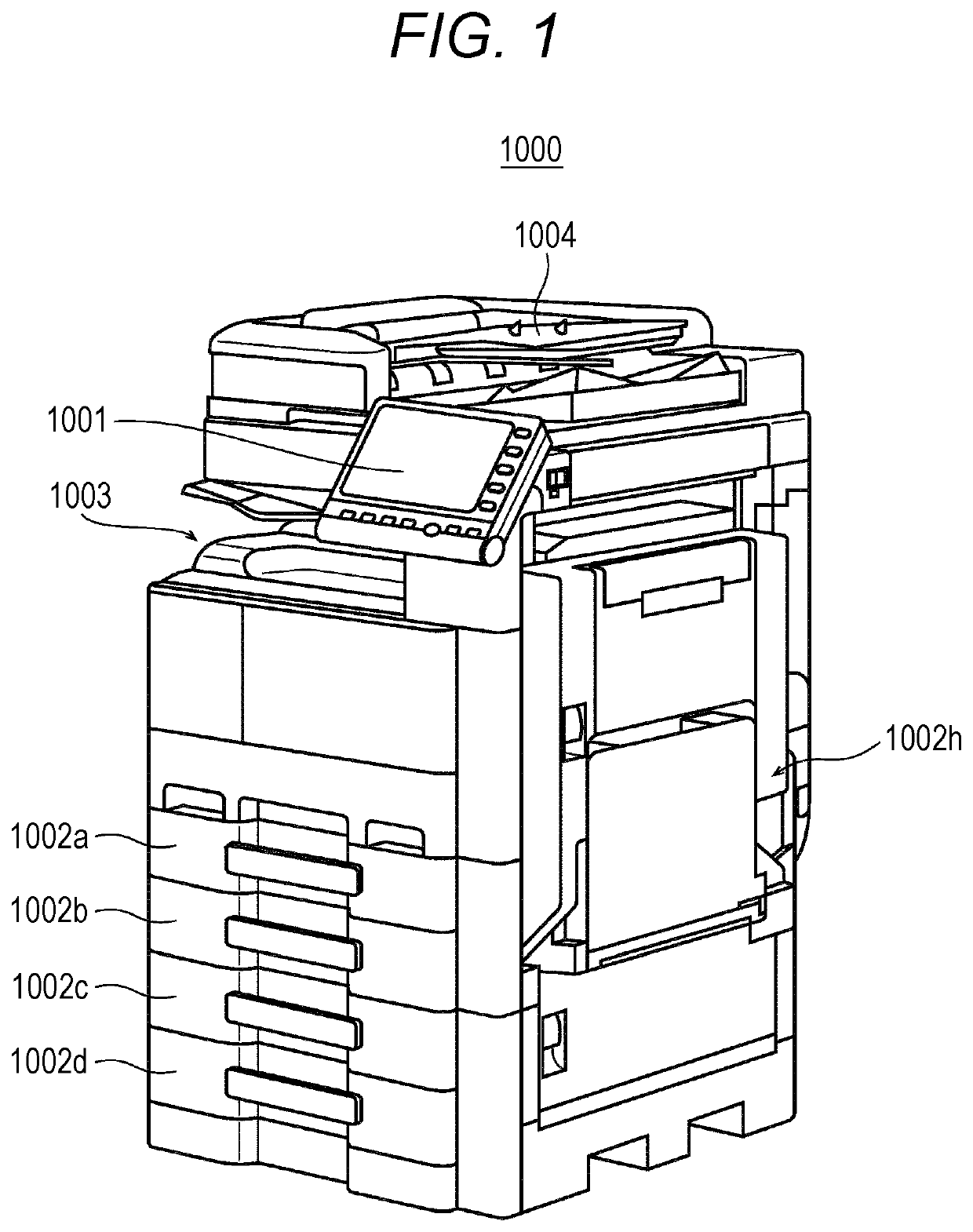
[0043]FIG. 1 is a view illustrating an external view of an image forming apparatus 1000 that is an MFP.

[0044]The image forming apparatus 1000 feeds, in accordance with operation by a user made on a touch panel display 1001, sheets set on sheet feeding cassettes 1002a, 1002b, 1002c, and 1002d, and a manual feeding tray 1002h while forming images on each photoconductor, transfers a toner image that has been formed on each photoconductor to a sheet, and ejects the sheet to an ejection tray 1003. During the sheet feeding, the image forming apparatus 1000 performs: double feed determination to determine whether or not two or more sheets are fed in an overlapping manner from the sheet feeding cassettes 1002a, 1002b, 1002c, and 1002d, and the manual feed...

second embodiment

[7] Outline of Second Embodiment

[0119]Control using an increase tendency look-up table 106T by a noise analyzer 106 described in an above-described embodiment is control that does not utilize feedback from an image forming apparatus 1000 and is performed by using only a control system assumed in the increase tendency look-up table 106T. In the control theory, such control is classified as open-loop control. However, such open-loop control has a problem of having a deviation between an actual operating state of the image forming apparatus 1000 and content of the increase tendency look-up table 106T.

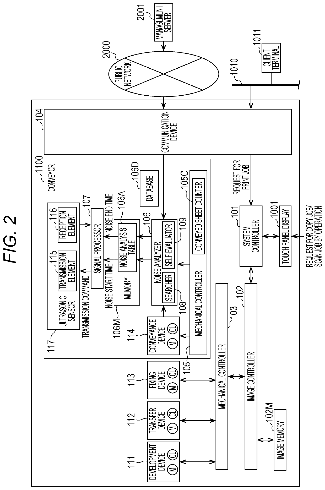
[0120]Accordingly, a self-evaluator 109 of a conveyor 1100 illustrated in FIG. 2 adjusts, in accordance with deterioration caused by use of the conveyor 1100, the increase tendency look-up table 106T that has been downloaded from a management server 2001. For such adjustment, the increase tendency look-up table 106T according to a second embodiment includes reference waveform data 106S.

[8]...


PUM


Abstract

A conveyor conveys a sheet along a conveyance path provided with an ultrasonic sensor, and includes: an updating member that successively updates a parameter indicating aged deterioration of the conveyor; a searcher that searches a look-up table storing pieces of noise data of noises predicted to be superimposed on a detection signal of the ultrasonic sensor in accordance with a degree of the aged deterioration, and obtains a piece of noise data corresponding to a current parameter value of the conveyor; and a signal processor that uses, for signal processing, a remaining portion of the detection signal of the ultrasonic sensor excluding a portion corresponding to the piece of noise data obtained by the searcher.

Description

CROSS-REFERENCE TO RELATED APPLICATION[0001]The present invention claims priority under 35 U.S.C. § 119 to Japanese Application No. 2019-160089, filed on Sep. 3, 2019, the entire content of which is incorporated herein by reference.BACKGROUNDTechnological Field[0002]The present invention relates to a conveyor that conveys a sheet through a conveyance path provided with an ultrasonic sensor, and particularly, relates to improvement in signal processing applied to a detection signal detected by the ultrasonic sensor.Description of the Related Art[0003]An ultrasonic sensor in the above-described conveyor includes a set of a transmission element and a reception element facing each other interposing a conveyance path therebetween. When an ultrasonic wave is transmitted during sheet conveyance in the conveyance path provided with the ultrasonic sensor, a detection signal output from the reception element of the ultrasonic sensor is attenuated due to passage of a conveyed object. That is, ...

Claims


Application Information

Patent Timeline
IPC IPC(8): B65H7/12B41F33/02G01S15/10
CPCB65H7/125B65H2553/30G01S15/101B41F33/02G01S15/88B65H5/062B65H2515/82B65H2601/121B65H2601/423B65H2557/33B65H2557/31B65H7/02B65H2511/416B65H2511/524B65H2557/23B65H2557/61B65H2557/64G03G15/55G03G2215/00637
Inventor HIGASHI, TOSHIKAZUEGUCHI, TATSUYAWATANABE, TAKASHIKATO, SHIGETAKAISHIDA, TAKESHI
Owner KONICA MINOLTA INC
Why Eureka
Try Eureka