
Electric compressor

Pending Publication Date: 2021-03-04
TOYOTA IND CORP
View PDF0 Cites 0 Cited by
  • Summary
  • Abstract
  • Description
  • Claims
  • Application Information

AI Technical Summary

Benefits of technology

The present invention relates to an electric compressor for compressing refrigerant in a refrigeration system. The compressor includes a housing, a drive shaft, a motor, a fixed scroll, a movable scroll, a fixed block, and a balance weight. The drive shaft is fixed in the housing and rotates to compress refrigerant. The motor is fixed in the housing and rotates the shaft. The fixed scroll is fixed in the housing and revolves with the shaft. The movable scroll is connected to the shaft and revolves to compress the refrigerant. The fixed block supports the shaft and is positioned between the motor and the movable scroll. The housing has an inlet to draw in refrigerant. The motor includes a stator and a rotor, and the rotor has a passage through which refrigerant flows. The balance weight is positioned between the fixed block and the motor to keep the motor stable during operation. The technical effects of this invention include improved compressor performance and stability, as well as reduced noise and vibration.

Problems solved by technology

However, if the housing of the compressor therefore becomes compact, it is difficult for the compressor to secure a space for the introduction passage between the housing and the fixed block in the motor chamber.
However, the rotor is disposed in the stator, so that it is unlikely that the refrigerant flowing through the introduction passage in the rotor can cool the stator suitably.
Accordingly, the stator may generate heat, which may lead to a decrease in the durability of the compressor.

Method used


Image

  • Electric compressor
  • Electric compressor
  • Electric compressor

Examples


Embodiment Construction

[0017]The following will describe an embodiment of the present disclosure in detail with reference to the accompanying drawings. A compressor according to the embodiment is, specifically, an electric scroll compressor. This scroll compressor is mounted in a vehicle (not illustrated) and included in a refrigerant circuit of the vehicle.

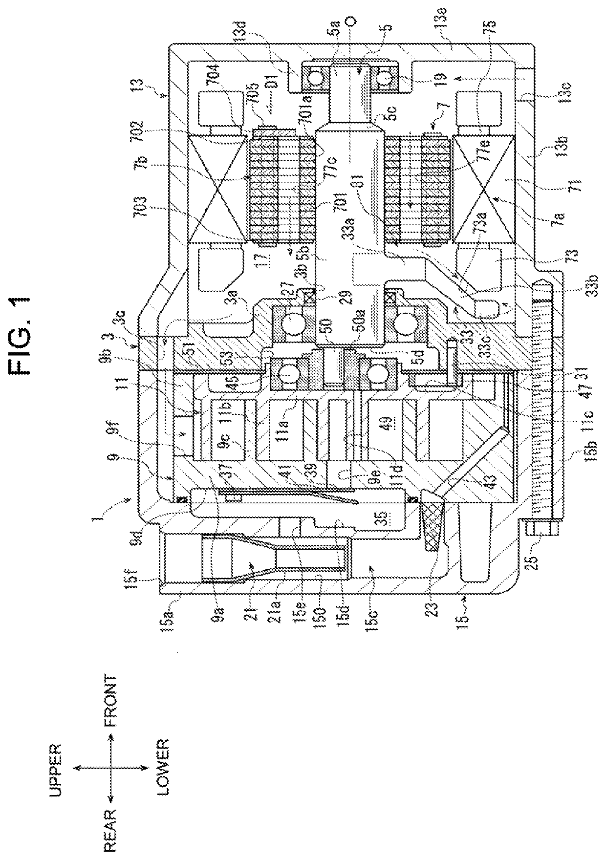
[0018]As illustrated in FIG. 1, the compressor according to the embodiment includes a housing 1, a fixed block 3, a drive shaft 5, a motor 7, a fixed scroll 9, and a movable scroll 11. The housing 1 includes a motor housing 13 and a compressor housing 15. FIG. 1 illustrates the drive shaft 5, the motor 7, and the like in a simplified shape for the sake of explanation. The same is true in FIG. 3 that will be described later.

[0019]As illustrated in FIG. 1, in the present embodiment, the front-rear direction of the compressor is defined by referring to the side on which the motor housing 13 is positioned as the front side of the compressor and referring t...


PUM


Abstract

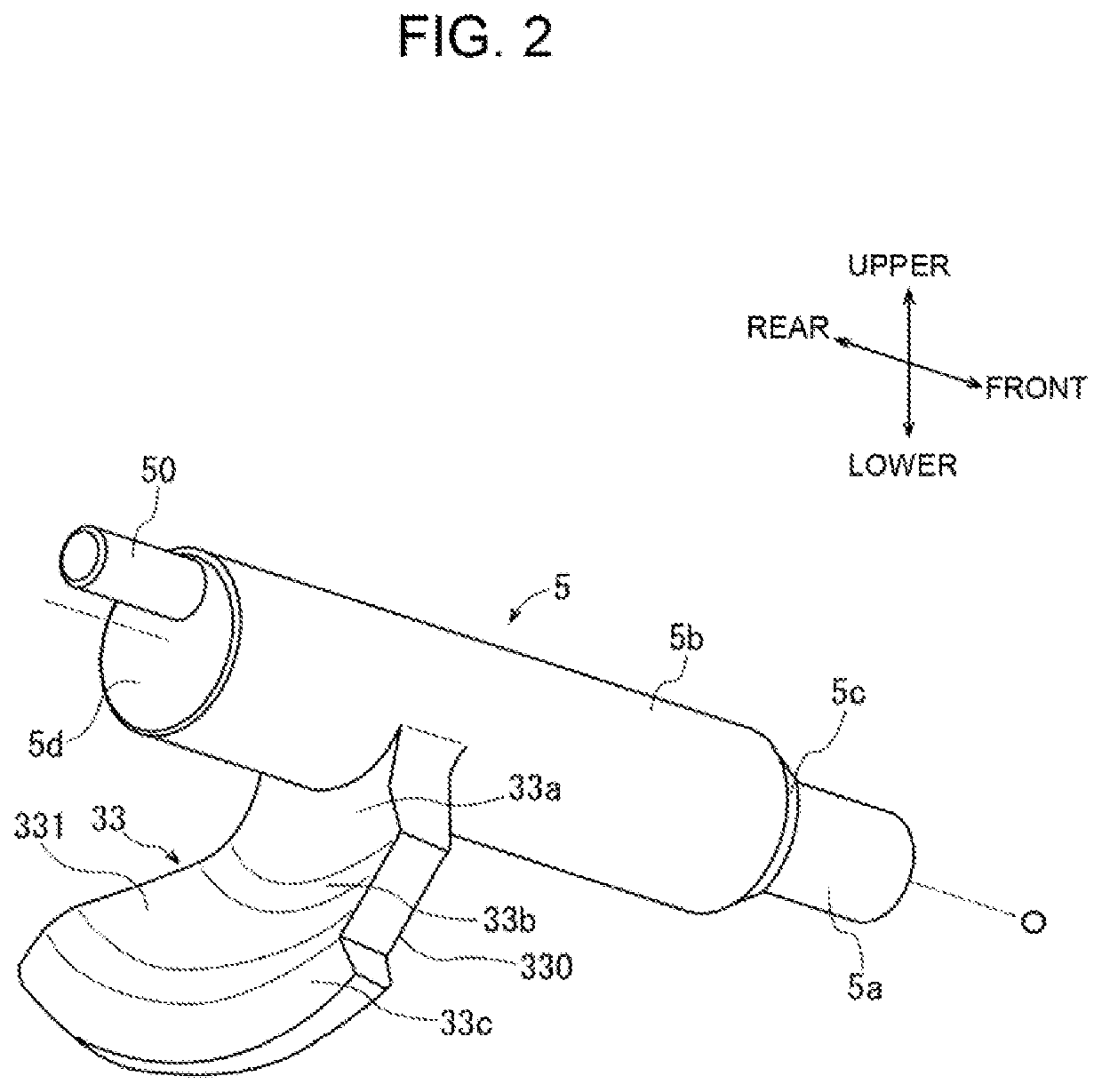
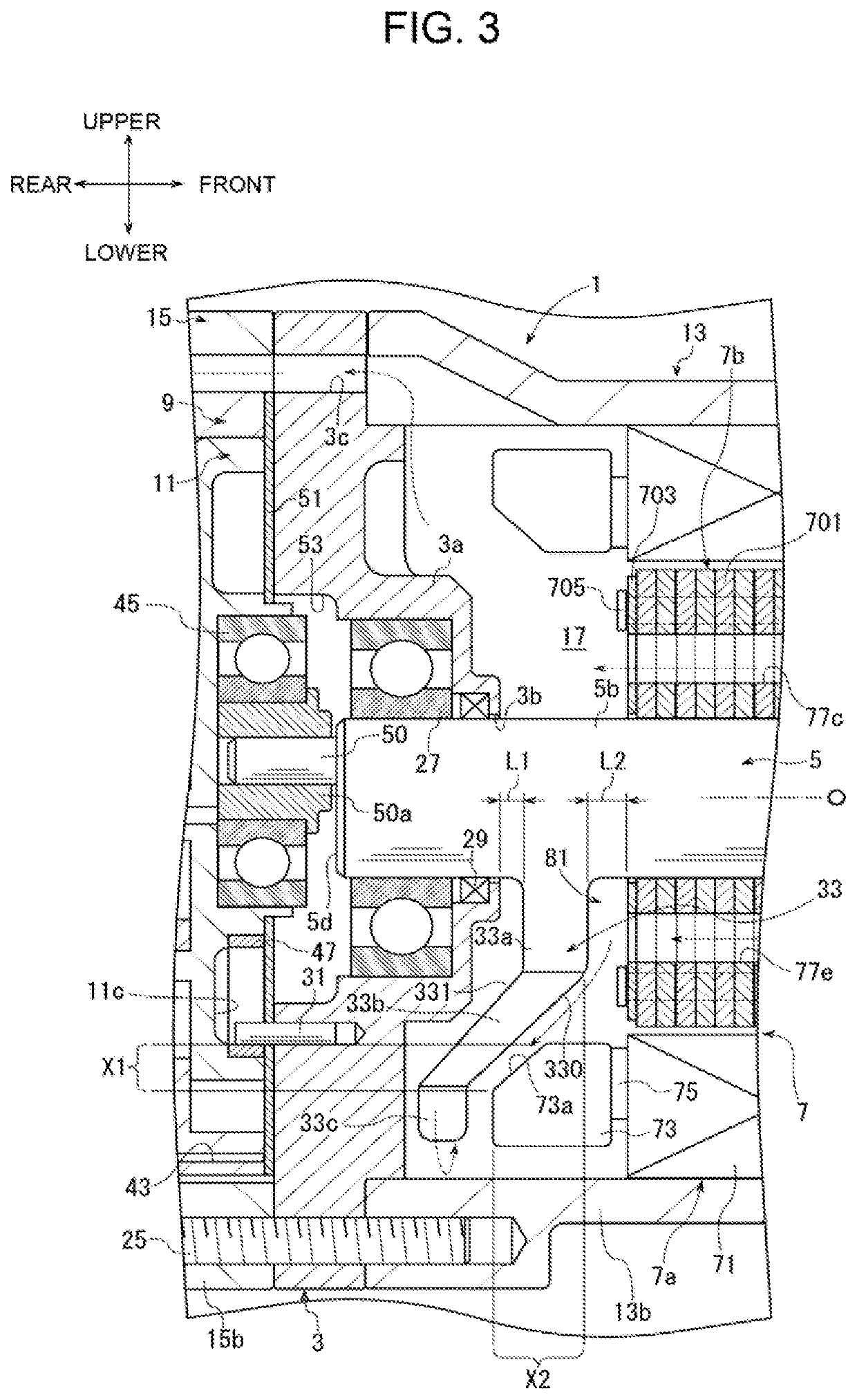
An electric compressor includes a housing, a drive shaft, a motor, a fixed scroll, a movable scroll, and a fixed block. The fixed block is fixed to the housing and disposed between the motor and the movable scroll. The motor includes a stator and a rotor. The rotor has an introduction passage that is formed through the rotor in an axial direction of the drive shaft. The drive shaft includes a balance weight that is disposed between the fixed block and the motor. The balance weight extends to a position where the balance weight covers at least a part of the introduction passage in a radial direction of the drive shaft in a view in the axial direction of the drive shaft. The balance weight is located away from the rotor by a predetermined distance in the axial direction of the drive shaft.

Description

[0001]This application claims priority to Japanese Patent Application No. 2019-157611 filed on Aug. 30, 2019, the entire disclosure of which is incorporated herein by reference.[0002]The present disclosure relates to an electric compressor.BACKGROUND ART[0003]Japanese Patent Application Publication No. 02-91489 discloses a known electric compressor (hereinafter simply referred to as a compressor). This compressor includes a housing, a drive shaft, a motor, a fixed scroll, a movable scroll, and a fixed block.[0004]The drive shaft is disposed in the housing, and is rotatable around an axis of the drive shaft. The motor is disposed in the housing, and rotates the drive shaft. The fixed scroll is fixed to the housing, and is disposed in the housing. The movable scroll is disposed in the housing and connected to the drive shaft. The movable scroll is engaged with the fixed scroll, and a compression chamber is formed between the movable scroll and the fixed scroll. The fixed block is fixe...

Claims


Application Information

Patent Timeline
IPC IPC(8): F04C18/02F04C23/00
CPCF04C18/0215F04C23/008F04C2240/807F04C2240/40F04C2240/30F04C2240/60F04C23/02F16F15/26F16F2222/08F04C2240/52F04C2240/20
Inventor HATTORI, YUYAYAMASHITA, TAKUROMAEDA, TAKUMI
Owner TOYOTA IND CORP
Learn More