Method for setting control parameters for model prediction control
- Summary
- Abstract
- Description
- Claims
- Application Information
AI Technical Summary
Benefits of technology
Problems solved by technology
Method used
Image


Examples
application example
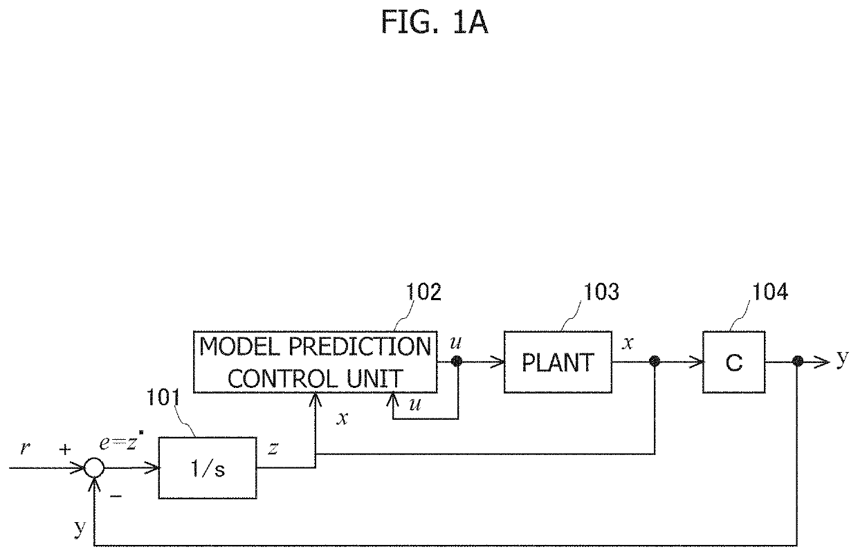
[0039]An example of a scene in which a method for setting control parameters for model prediction control according to the present invention is applied will be described with reference to FIGS. 1A to 1C. FIG. 1A illustrates a control structure that executes tracking control (servo control) for causing an output y of a plant 103 which is a control target to track a target command r. In the control structure, model prediction control is executed by the model prediction control unit 102, whereby tracking control to the target command r is realized, a control input to the plant 103 calculated by the model prediction control is referred to as u, and a state variable related to the plant 103 used for calculation of the model prediction control is referred to as x.
[0040]In the control structure, an offset e (e=r−y) between the target command r and the output y of the plant 103 is input to a first integrator 101. An output z of the first integrator 101 is also included in the state variable...
first configuration example
[0059]FIG. 2 is a diagram illustrating an overall configuration of a control system according to a first configuration example. The control system includes a network 1, a servo driver 4, and a standard PLC (Programmable Logic Controller) 5. The servo driver 4 is a control device that executes model prediction control for servo-controlling an actual plant (hereinafter simply referred to as an “actual plant”) 6 including a motor 2 and a load device 3. In the control system, the servo driver 4 performs servo control involving model prediction control with respect to the actual plant 6 so that the output of the actual plant 6 tracks a target command transmitted from the standard PLC 5. With this model prediction control, the servo driver 4 generates a control input for performing servo control of the actual plant 6 on the basis of the target command received from the standard PLC 5. Generation of the control input by the servo driver 4 will be described later. In this case, examples of ...
second configuration example
[0091]Servo control by the servo driver 4 according to a second configuration example will be described with reference to FIG. 6. In the servo driver 4 of this configuration example, the expanded plant 60 including the actual plant 6 is formed similarly to the first configuration example, model prediction control is performed by the model prediction control unit 43, and the output z of the first integrator 41 is acquired by the state acquisition unit 42 and is provided to the model prediction control. In this configuration example, the second integrator 6a and the actual plant 6 are combined to form the expanded plant 60 as illustrated in the lower part (b) of FIG. 6.
[0092]In the expanded plant 60 of the present embodiment, the control input u is a jerk input (dτ / dt). When an expanded state variable related to the expanded plant 60 is represented by Equation 30 below, the prediction model of the model prediction control unit 43 can be represented by Equation 31 below.
[Math.28]x=[x1x...
PUM
 Abstract
Description
Claims
Application Information
 - R&D
- Intellectual Property
- Life Sciences
- Materials
- Tech Scout
- Unparalleled Data Quality
- Higher Quality Content
- 60% Fewer Hallucinations
Browse by: Latest US Patents, China's latest patents, Technical Efficacy Thesaurus, Application Domain, Technology Topic, Popular Technical Reports.
© 2025 PatSnap. All rights reserved.Legal|Privacy policy|Modern Slavery Act Transparency Statement|Sitemap|About US| Contact US: help@patsnap.com