
Signal Acquisition Device for Acquiring Three-Dimensional (3D) Wave Field Signals

a wave field signal and signal acquisition technology, applied in the field ofsignal processing, can solve the problems of increasing the complexity of construction, requiring the use of first-order sensors, and the array type is costly to implement, so as to reduce computational costs

Pending Publication Date: 2021-03-04
HARPEX AUDIO GMBH
View PDF5 Cites 0 Cited by
  • Summary
  • Abstract
  • Description
  • Claims
  • Application Information

AI Technical Summary

Benefits of technology

The patent describes a way to determine the pattern of sound waves by measuring the pressure on two surfaces. This is done by using two two-dimensional arrays of sensors to measure the difference between signals. By measuring the pressure on both surfaces, the system can determine if the sound waves are even or odd modes. Even modes cause no vibration or scattering, while odd modes cause both vibration and scattering. The system can accurately model these processes and estimate the incident wave field based on the measured pressure on the two surfaces. Overall, this technique provides a way to accurately measure the pattern of sound waves.

Problems solved by technology

This, combined with the practical difficulties in assembling electronics in a spherical form, makes this type of array costly to implement, particularly when a broad frequency range is required.
However, the improvements that such arrays bring in terms of bandwidth come at the cost of further increased complexity in construction.
It has the disadvantage, however, that it requires the use of first-order sensors.
The use of standard PCB production techniques like reflow soldering is precluded due to the low temperature tolerance of the currently available low-cost first-order sensors.
However, the low-frequency first-order sensitivity of such sensor pairs is such that the low-frequency limit of the entire system would in that case be governed by the distance between sensors within each pair rather than the much larger distance between sensors at different locations in the plane.
In any real implementation, these elements would necessarily scatter the wave field to some extent, thereby reducing the accuracy of the constructed wave field representation.
While this geometry is also capable of capturing the information necessary to obtain a spherical harmonic decomposition of the 3D wave field, the practical implementation of such a 3D structure is more challenging than implementing a 2D microphone array and the resulting structure will be less portable and robust, particularly as it needs to be acoustically open.
This arrangement is, however, not intended to capture 3D wave field signals or to construct a 3D wave field representation.
This microphone array only has sensors on one side of the PCB and is only capable of producing a 2D wave field representation.

Method used


Image

  • Signal Acquisition Device for Acquiring Three-Dimensional (3D) Wave Field Signals
  • Signal Acquisition Device for Acquiring Three-Dimensional (3D) Wave Field Signals
  • Signal Acquisition Device for Acquiring Three-Dimensional (3D) Wave Field Signals

Examples


specific embodiment

[0072]In a specific embodiment, referring to the cross section in FIG. 9, the invention comprises the following parts: A circular PCB made from the composite material FR-4 (1), with a thickness of 1.55 mm. The PCB has a diameter of 170 mm and is coated with an 18 μm thick layer of copper (2) forming the electrical connections between the components. The copper layers are in coated with a 20 μm thick epoxy-based solder mask (not shown). Electronic components are soldered to the circuit board. Each side of the circuit board is covered by a 0.5 mm thick protective sheet of polypropylene (4), deep drawn and drilled to provide openings (7) for electrical connectors (not shown) and the acoustic ports (6) of the microphones (5) and a piezo-electric transducer (not shown). The space between the circuit board and the polypropylene sheet is filled with epoxy resin (3). In this embodiment, the reflective plate consists of all the layers and components from and including the one sheet of polypr...


PUM


Abstract

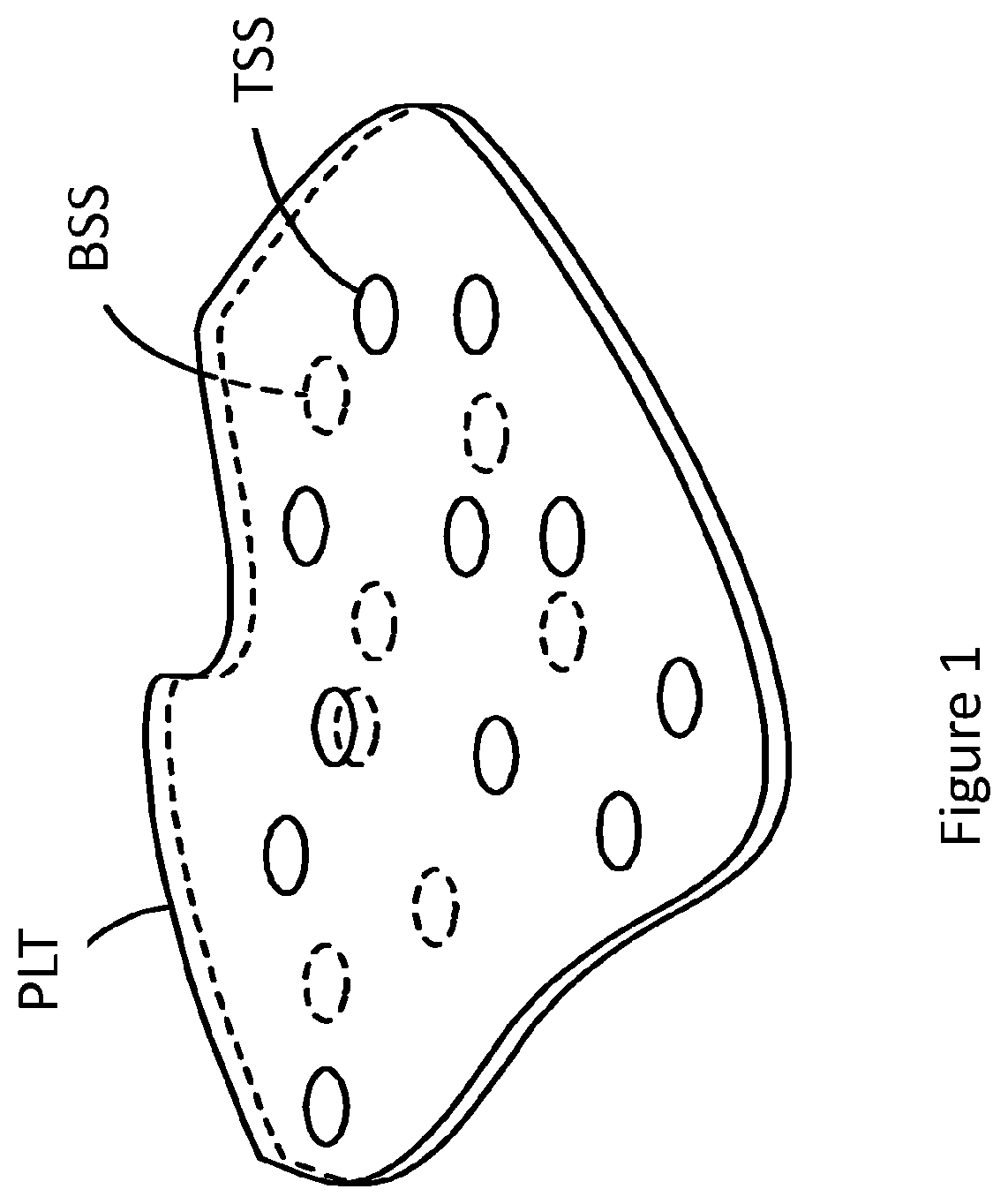
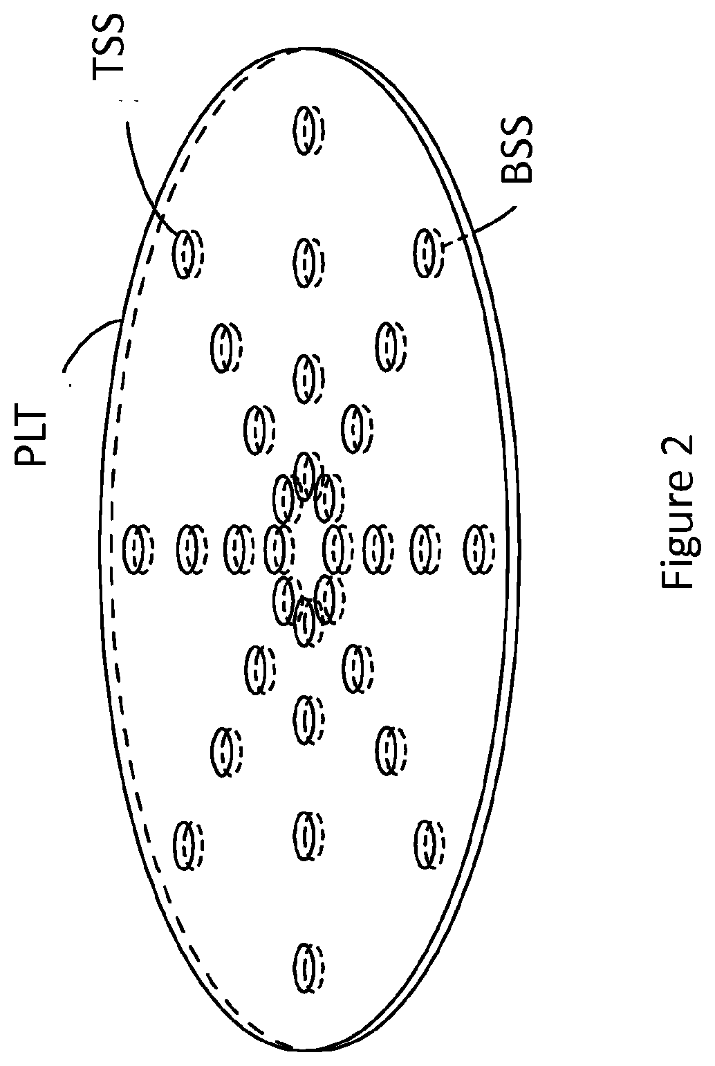
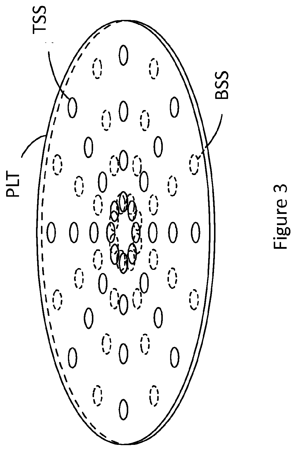
A Signal acquisition device is described for acquiring three-dimensional wave field signals. The signal acquisition device comprises an acoustically reflective plate (PLT) comprising two planar sides facing oppositely and a two-dimensional array of inherently omnidirectional sensors (TSS) arranged on one of the two sides, characterized in that the sound recording device comprises another two-dimensional array of inherently omnidirectional sensors (BSS) arranged on the other of the two sides.

Description

[0001]The present invention relates generally to the field of signal processing and, in particular, to acquiring three-dimensional (3D) wave field signals.BACKGROUND[0002]In the field of signal processing, it is desirable to obtain a 3D wave field mathematical representation of the actual 3D wave field signals as such a representation enables an accurate analysis and / or reconstruction of the 3D wave field. One such mathematical representation is the 3D wave field spherical harmonic decomposition.[0003]Several microphone array geometries, sensor types and processing methods have been proposed in order to capture and process the information required for producing such a representation. A spherical array of pressure microphones placed flush with the surface of a rigid sphere is capable of capturing information which can be transformed into a spherical harmonic decomposition of the 3D wave field. This arrangement is described in Meyer, J.; Elko, G.: A highly scalable spherical microphon...

Claims


Application Information

Patent Timeline
IPC IPC(8): H04R3/00H04R1/40H04S3/00
CPCH04R3/005H04R1/406H04S2420/11H04R2201/401H04S2400/15H04S3/002
Inventor BERGE, SVEIN
Owner HARPEX AUDIO GMBH
Learn More