Lock device for pipe coupling and valve coupling part

a technology of valve coupling and lock device, which is applied in the direction of hose connections, couplings, screw threaded joints, etc., can solve the problems of posing a great risk of raw material leakage, and achieve the effect of preventing accidental external forces from loosening and erroneous operation of the coupling, preventing the mutual rotation of the coupling parts, and ensuring the safety of the user

Active Publication Date: 2021-03-11
KITZ SCT
View PDF0 Cites 0 Cited by
  • Summary
  • Abstract
  • Description
  • Claims
  • Application Information

AI Technical Summary

Benefits of technology

The invention is a device for securely attaching a coupling part of a piping or valve to a raw-material container or the like. The device includes a clamp member for positioning and fixing and a clamp member for additional fastening. These clamp members are fastened together with a screw member, preventing mutual rotation of the coupling parts and ensuring stability and reliability. The attachment can be easily made without removing the coupling part from the pipe path, and the device provides a firm and secure fastening. The invention also includes a design with parallel engaging surfaces that allow for easy attachment and prevent rotation of the coupling. The device can be easily attached to the valve body or the female nut without machining the existing coupling. Overall, the invention provides a reliable and convenient attachment for various applications.

Problems solved by technology

In this case, since many liquid materials for use as raw materials for semiconductor manufacture have a very hazardous property such as toxicity, the raw-material container is required to be strictly sealed so that the raw material does not leak to outside.
However, in the event that the coupling is loosened by vibration, impact, or inadvertent external forces during transportation or storage of the raw-material container or that an inexperienced operator mistakenly operates the coupling when handling the raw-material container in the field, the raw material may leak to pose a great hazard, and this leakage of the raw material may lead to a serious accident.

Method used


Image

  • Lock device for pipe coupling and valve coupling part
  • Lock device for pipe coupling and valve coupling part
  • Lock device for pipe coupling and valve coupling part

Examples


first embodiment

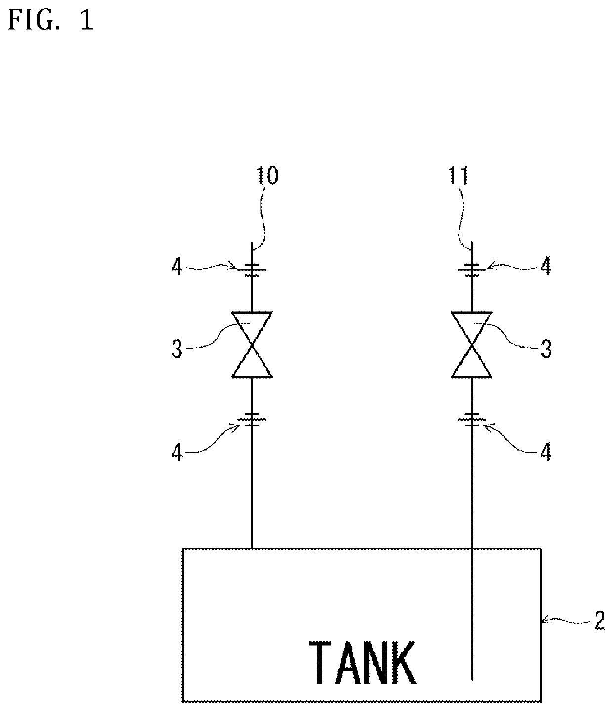
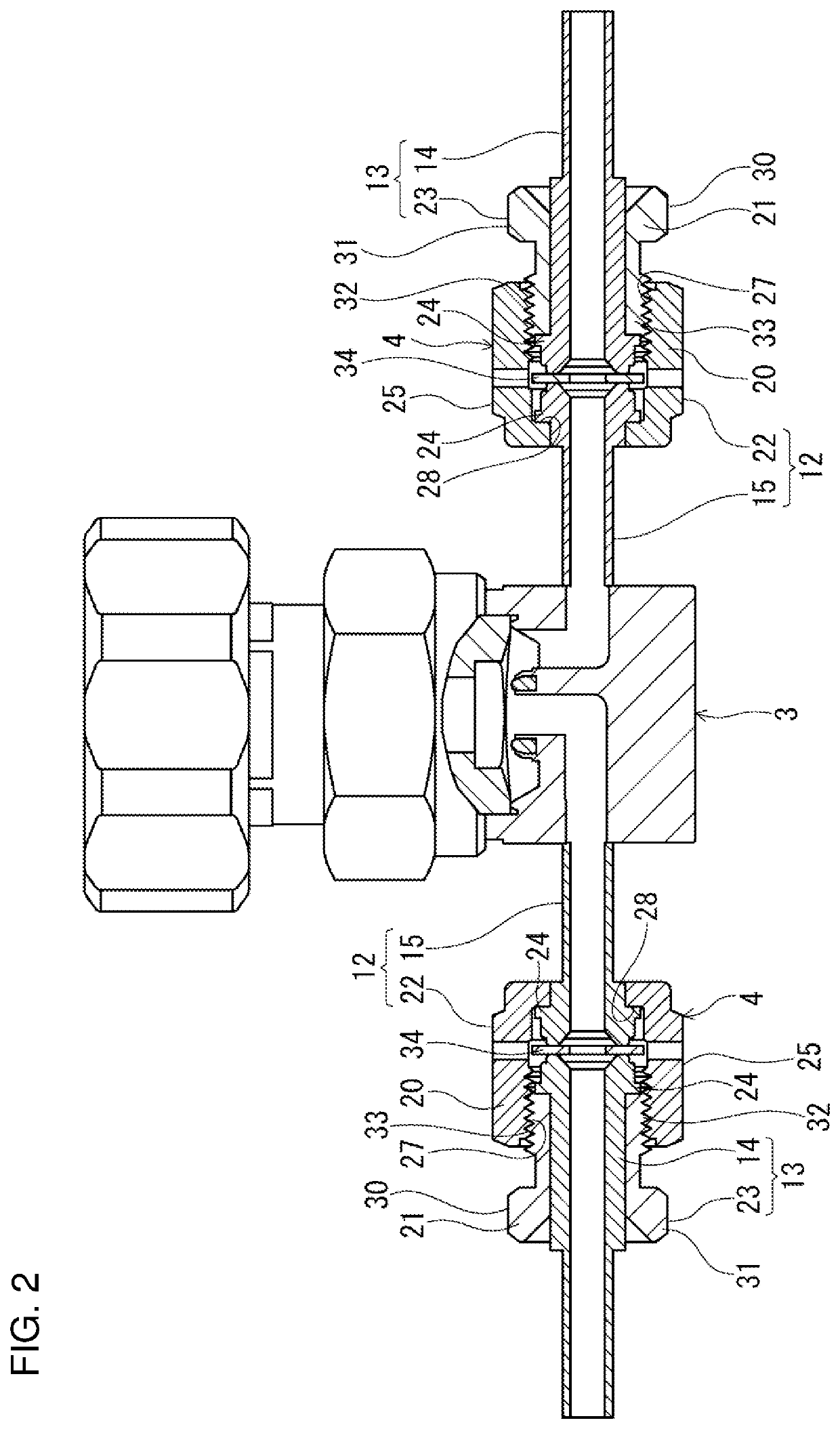
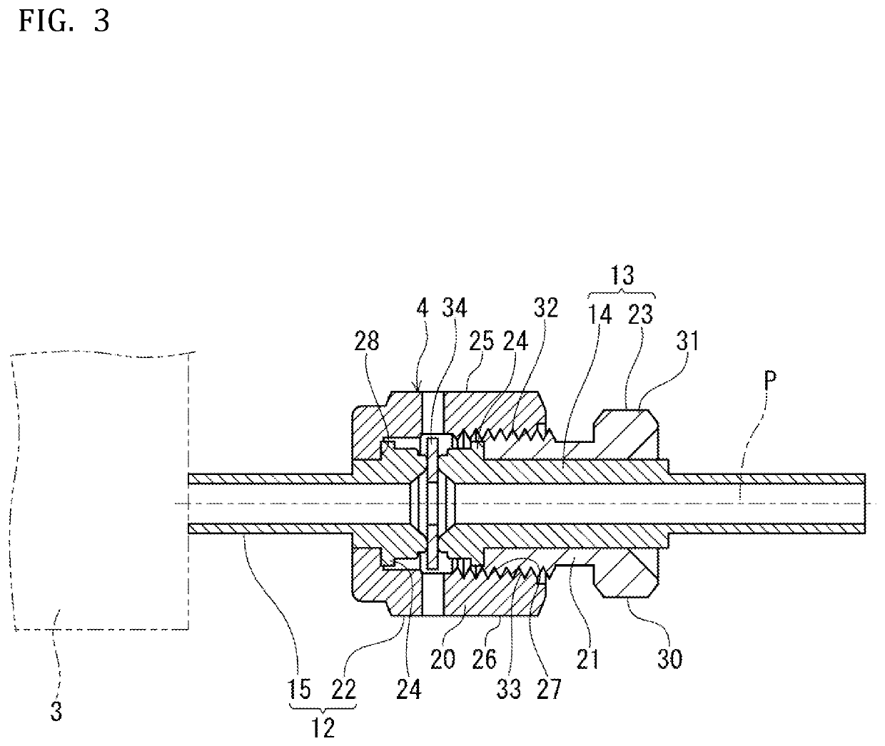
[0046]In the following, embodiments of the lock device for the pipe coupling and the valve coupling part of the present invention are described in detail based on the drawings. FIG. 1 is a general schematic view depicting one example of a raw-material container, FIG. 2 is a partially-cutout front view depicting a pipe coupling and a valve coupling part in FIG. 1, and FIG. 4 depicts the lock device for the pipe coupling and the valve coupling part in the present invention. First, a raw-material container 2, a valve main body 3, and a coupling part 4 are described, for which the lock device (hereinafter referred to as a device main body 1) for the pipe coupling and the valve coupling part is used.

[0047]The raw-material container 2 depicted in FIG. 1 is used in, for example, a semiconductor manufacturing process. This raw-material container 2 is provided with an introduction flow path 10 which introduces a fluid to the inside and a discharge flow path 11 which discharges the inner flui...

second embodiment

[0077]Depicted in FIG. 7 is another example of the pipe coupling. Depicted in FIG. 8 and FIG. 9 is the lock device for the pipe coupling and the valve coupling part of the present invention. Note in this embodiment that a portion identical to that of the above-described embodiment is denoted by the same reference numeral and its description is omitted.

[0078]In this embodiment, when the coupling part 4 is configured onto a valve body 81 of a valve main body 80, a screwed member 82 has the male nut 23, a screwing member 83 has the female nut 22 in a cap-nut shape, and the connecting pipe 14 is connected via these male nut 23 and female nut 22. That is, the male nut 23 is provided on a valve main body 80 side as a screwed side and the female nut 22 is provided on an external coupling side as a screwing side.

[0079]In FIG. 8 and FIG. 9, a device main body 90 includes a second clamp member 42 for additional fastening, which is a component common to that in the above-described embodiment; ...


PUM


Abstract

A lock device for a coupling part of a piping or valve of a raw-material container or the like, capable of preventing looseness and erroneous operation of a coupling, and having favorable stability because the device is fixed as a force is applied to a direction of additionally fastening the coupling. The lock device is provided for achieving prevention of looseness of a coupling part (4) formed of a screwed member (20) and a screwing member (21) side, and includes a clamp member (42) for additional fastening attached to the screwed member side, a clamp member (41) for positioning and fixing attached to the screwing member side, and a screw member (43) for fastening the clamp members. The clamp members are fastened with the screw member (43), thereby being fixed to the coupling part while a force is applied to a direction of additionally fastening the screwing member side.

Description

TECHNICAL FIELD[0001]The present invention relates to a lock device for a pipe coupling and a valve coupling part to prevent looseness after the pipe coupling and the coupling part of the valve are fastened.BACKGROUND ART[0002]Conventionally, in a semiconductor manufacturing process, for example, a raw-material container for accommodating a raw material for semiconductor manufacture is generally used. In this case, since many liquid materials for use as raw materials for semiconductor manufacture have a very hazardous property such as toxicity, the raw-material container is required to be strictly sealed so that the raw material does not leak to outside. On the upper surface of the raw-material container of this type, a valve and a piping for supplying the raw material and purge gas are normally installed via couplings. For transportation, storage, and so forth of the raw-material container, the raw-material container is hermetically sealed so that the raw material does not leak out...

Claims


Application Information

Patent Timeline
IPC IPC(8): F16L15/08F16K51/00
CPCF16L15/08F16K51/00F16L19/025F16L19/0212F16L2201/20F16L33/24
Inventor KOGURE, YUSAKU
Owner KITZ SCT
Why Eureka
Try Eureka