Check patentability & draft patents in minutes with Patsnap Eureka AI!

Inrush current test device

Active Publication Date: 2021-03-11
CHICONY POWER TECH CO LTD
View PDF0 Cites 0 Cited by
  • Summary
  • Abstract
  • Description
  • Claims
  • Application Information

AI Technical Summary

Benefits of technology

The inrush current test device is designed to accurately provide an inrush current to an electronic device for testing. It generates a positive crossing point pulse based on the alternating current and outputs a test power in a reference phase. A high and low voltage compensation device corrects the alternating current and outputs a compensation power with the same voltage rising slope. This ensures that the inrush current test device uses the compensation power with the same voltage rising slope for phase calculation, regardless of the input alternating current's mode (high or low). This reduces the phase error and ensures accurate phase measurement.

Problems solved by technology

The inrush current is usually much greater than a steady-state current, and consequently components in the electronic device may be damaged due to the inability to withstand the inrush current.
When the inrush current is greater, the components in the electronic device are more likely to be damaged.
If the electronic device cannot be tested with a maximum peak inrush current or appropriate parts cannot be selected, a protection circuit of an insufficient specification may be manufactured.
Because a rising slope or falling slope of an input sine wave of the high voltage and that of the low voltage are different, there may be errors in circuit parameters of the electronic device, and consequently the electronic device cannot be accurately applied according to the design concept.
However, when there is a difference in the rising slope or falling slope of the input sine wave of the mains voltage, a phase detection time may be delayed or advanced, and consequently a detection signal for the zero crossing point of the mains sine wave is not absolutely accurate.
As a result, this causes great inconvenience to the daily use of the electronic device.

Method used


Image

  • Inrush current test device
  • Inrush current test device
  • Inrush current test device

Examples


Embodiment Construction

[0022]In the present invention, the word “coupling” and its derivatives are used. In some embodiments, “coupling” may be used to indicate that two or more components are in direct physical or electrical contact with each other, or may also mean that two or more components are in indirect electrical contact with each other. The word “coupling” can still be used to indicate that two or more components collaborate or interact with each other.

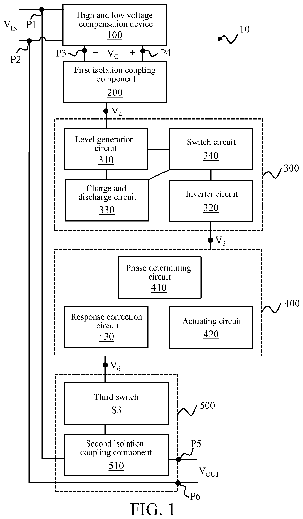
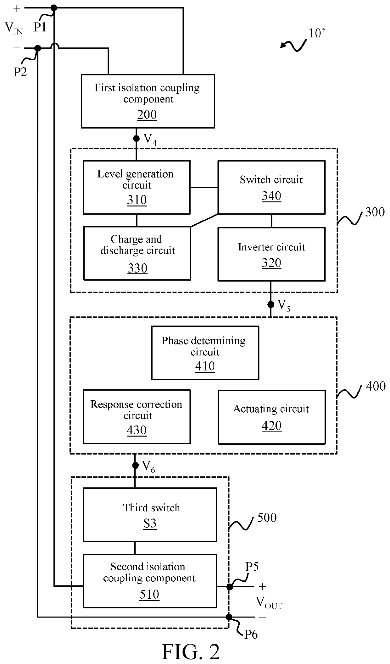
[0023]FIG. 1 is a block diagram of an inrush current test device 10 according to some embodiments of the present invention, and FIG. 2 is a block diagram of an inrush current test device 10′ according to some embodiments of the present invention. Referring to FIG. 1 and FIG. 2, in some embodiments, the inrush current test device 10 (10′) is adapted to receive an alternating current VIN, and output a test power VOUT according to the alternating current VIN in a reference phase. The reference phase is, for example but not limited to, 90 degrees, 270 ...


PUM


Abstract

An inrush current test device is adapted to receive an alternating current. The inrush current test device includes: a first isolation coupling component, a positive crossing point pulse generation circuit, an output circuit, and a control circuit. The first isolation coupling component includes a primary side and a secondary side, and is responsive to the alternating current on the primary side and conducts the secondary side. When the secondary side transits from an off state to an on state, the positive crossing point pulse generation circuit generates a positive crossing point pulse. When the control circuit is actuated and the positive crossing point pulse is detected, after delaying for a delay time, the control circuit outputs a control pulse for actuating the output circuit for a first operating time. The output circuit is configured to receive the alternating current and output the alternating current when the output circuit is actuated.

Description

CROSS-REFERENCE TO RELATED APPLICATION[0001]This non-provisional application claims priority under 35 U.S.C. § 119(a) to Patent Application No. 108132330 filed in Taiwan, R.O.C. on Sep. 6, 2019, the entire contents of which are hereby incorporated by reference.BACKGROUNDTechnical Field[0002]The present invention relates to the power supply field, and in particular, to an inrush current test device.Related Art[0003]An inrush current often occurs at the moment when an electronic device begins to input electricity. The inrush current is usually much greater than a steady-state current, and consequently components in the electronic device may be damaged due to the inability to withstand the inrush current. When the inrush current is greater, the components in the electronic device are more likely to be damaged.[0004]The inrush current may occur due to, for example, the following reason: a primary side circuit of an AC power supply includes an energy storage capacitor, and the moment whe...

Claims


Application Information

Patent Timeline
IPC IPC(8): G01R19/165G01R1/36G01R1/28
CPCG01R19/16547G01R1/28G01R1/36G01R19/0092H02H3/093
Inventor HSIAO, JEN-HAO
Owner CHICONY POWER TECH CO LTD
Features
  • R&D
  • Intellectual Property
  • Life Sciences
  • Materials
  • Tech Scout
  • Unparalleled Data Quality
  • Higher Quality Content
  • 60% Fewer Hallucinations
Learn More