
Multifunctional intensified reactor device with integrated heat and mass transfer

a multi-functional, intensified reactor technology, applied in the direction of separation process, chemical/physical/physico-chemical process, separation of dispersed particles, etc., can solve the problem that the decarbonization progress to achieve the ipcc's target of an average temperature increase of under 1.5° c. has not yet been successful, the methods investigated are prohibitively expensive or speculative, and have not yet been commercialized

Active Publication Date: 2021-03-18
UT BATTELLE LLC
View PDF0 Cites 6 Cited by
  • Summary
  • Abstract
  • Description
  • Claims
  • Application Information

AI Technical Summary

Benefits of technology

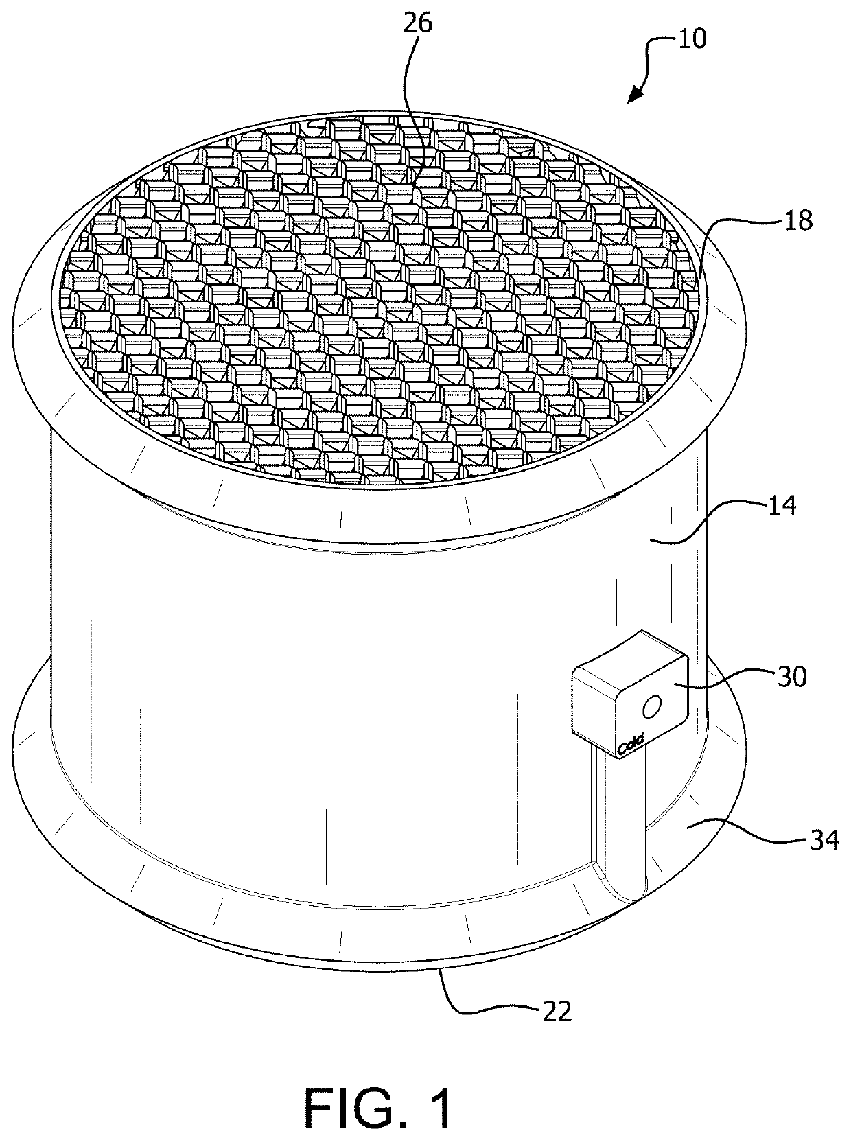
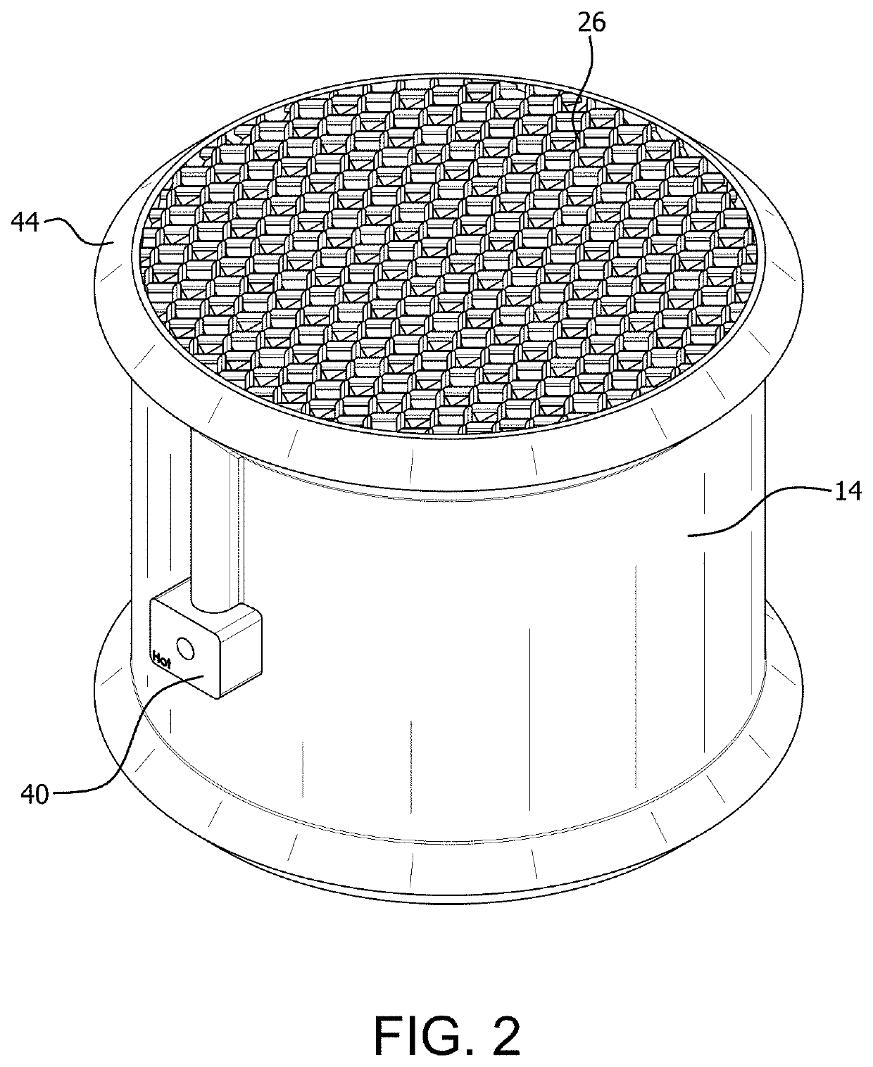
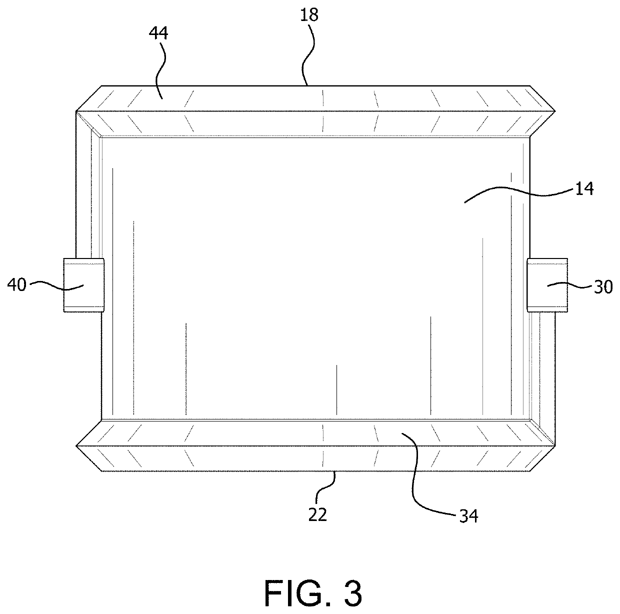
The patent describes a packing device for mass and heat transfer that can be used to transfer heat from a gas stream to a liquid. The device includes a housing with openings for the gas and liquid to flow through. The device includes mass and heat transfer plates with interior and exterior surfaces for contacting the gas and liquid. The plates have channels for the fluid to flow through and heat exchanger plates to transfer heat from the fluid to the gas. The device can be used in a countercurrent flow system, where the gas and liquid flow in opposite directions. The technical effects of the device include efficient heat transfer and separation of CO2 from the gas stream.

Problems solved by technology

Progress towards decarbonization to achieve the IPCC's target of an average temperature increase to below 1.5° C. has not yet been successful.
Some of the methods investigated, however, are prohibitively costly or speculative.
The technology, however, has not yet been commercialized, as the energy penalty and cost remain far from economically viable.
The prior art structures cannot perform, in an in-situ manner, either the removal of heat accumulated in the column due to an exothermic chemical reaction, nor the addition of heat to enhance the rate of an endothermic chemical reaction.
Despite being considered one of the least costly CO2 capture methods, absorption still imposes a substantial energy penalty on a power plant.
The energy required to pump the solvent and the energy required to compress CO2 after it exits the desorber also consume significant amounts of energy.
MEA has a heat-dependent tendency to degrade due to the formation of oxazolidones and diamines.
This risk limits the regeneration temperature, which increases the heat duty of the reboiler, and increases material costs by necessitating replacement of the solvent.
The pressure drop will determine the size of the blower needed since a higher pressure drop means a blower has to work harder to achieve the desired flow conditions.
The relatively high reaction rate of MEA with CO2 is desirable, but carries significant drawbacks.
The reverse reaction is useful for regenerating the solvent; however, it presents a problem for absorption because if the reaction temperature increases, the kinetics will favor desorption, thus inhibiting the absorption efficiency.
It is evident that the thermodynamics of the MEA absorption reaction pose one of the most significant hurdles to the widespread adoption of amine absorption technology.
This reaction is also highly exothermic which results in lower equilibrium and the formation of undesirable products.
The total pressure drop was relatively low, but the geometry of the design was not optimized and could yield yet lower pressure drop.
Almost anything that can be modeled using Computer Aided Design (CAD) can be manufactured, which gives engineers unparalleled design flexibility.
Such structures may have substantial advantages over conventional geometries, but they are prohibitively difficult to manufacture by conventional means due to their internal labyrinthine structure.

Method used


Image

  • Multifunctional intensified reactor device with integrated heat and mass transfer
  • Multifunctional intensified reactor device with integrated heat and mass transfer
  • Multifunctional intensified reactor device with integrated heat and mass transfer

Examples


example

[0090]A packing device according to the invention was manufactured at Oak Ridge National Laboratory's Manufacturing Demonstration Facility. Corrugated sheets were modeled in Solidworks and bundled together. The angle of corrugation can be altered, but for this experiment it was set to 45°. A cylindrical cut was then made on the stack of corrugated sheets. Previous studies have evaluated the hydrodynamic characteristics of 3D printed plastic packing elements of Mellapack geometry in comparison to those of metal and plastic commercial packing elements. It was found that 3D printed plastic packing elements had a pressure drop that compared favorably to both metal and plastic commercial packing elements; however, the wettability compared poorly to the metal commercial packing element which suggests selecting a more hydrophilic material would improve the performance of the device. For that reason, aluminum was chosen as the printing material in this study, as well as because of its high ...


PUM

PropertyMeasurementUnit
temperatureaaaaaaaaaa
massaaaaaaaaaa
acute angleaaaaaaaaaa

Abstract

A packing device for mass and heat transfer with a subject fluid includes a housing having opposing ends, and subject fluid openings at each opposing end defining a subject fluid flow path for at least one subject fluid flowing through the packing device. A plurality of mass and heat transfer plates each include an interior heat exchange fluid channel disposed between interior heat transfer surfaces of the mass and heat transfer plates. A heat exchange fluid inlet and fluid outlet can supply and remove heat exchange fluid to the heat exchange fluid channels of the mass and heat transfer plates. The mass and heat transfer plates can be oriented to define there between fluid flow channels for the subject fluid. A method and system for mass and heat transfer with a subject fluid, and a method and system for the removal of CO2 from a gas stream are disclosed.

Description

CROSS-REFERENCE TO RELATED APPLICATIONS[0001]This application claims priority to U.S. Provisional Patent Application No. 62 / 913,764 filed on Oct. 11, 2019, and U.S. Provisional Patent Application No. 62 / 866,018 filed on Jun. 25, 2019, both entitled “Multifunctional Intensified Reactor Device with Integrated Heat and Mass Transfer”, the entire disclosures of which are incorporated herein by reference.STATEMENT REGARDING FEDERALLY SPONSORED RESEARCH AND DEVELOPMENT[0002]This invention was made with government support under Contract No. DE-AC05-00OR22725 awarded by the U.S. Department of Energy. The government has certain rights in this invention.FIELD OF THE INVENTION[0003]The present invention relates generally to methods and apparatus for mass transfer, and more particularly to methods and apparatus for mass and heat transfer.BACKGROUND OF THE INVENTION[0004]In 2018, global CO2 emissions are estimated to have increased to 37.1±1.8 Gt per year, a 2.7% increase from the previous year....

Claims


Application Information

Patent Timeline
Patent Type & Authority Applications(United States)
IPC IPC(8): B01J19/32B01D53/14B01D53/18
CPCB01J19/32B01D53/1475B01D53/1493B01D53/18B01J2219/3325B01D2252/20489B01J2219/3221B01J2219/32275B01D2252/20484B01D2252/20478B01D2258/0283Y02C20/40Y02A50/20B01J2219/32237B01J2219/00763B01J2219/00873
Inventor LAI, CANHAILOVE, LONNIE J.PARKS, II, JAMES E.SUN, XINTSOURIS, CONSTANTINOSMATUSZEWSKI, MICHAEL
Owner UT BATTELLE LLC
Learn More