Thermal spray nozzle and plasma thermal spray device

Inactive Publication Date: 2021-03-25
MITSUBISHI HEAVY IND LTD
View PDF0 Cites 0 Cited by
  • Summary
  • Abstract
  • Description
  • Claims
  • Application Information

AI Technical Summary

Benefits of technology

The invention helps to speed up the heating and melting of thermal spray powder.

Problems solved by technology

If such a phenomenon occurs, only a partial thermal spray powder of the thermal spray powder put into the plasma flame cannot be heated and melted.

Method used


Image

  • Thermal spray nozzle and plasma thermal spray device
  • Thermal spray nozzle and plasma thermal spray device
  • Thermal spray nozzle and plasma thermal spray device

Examples


first embodiment

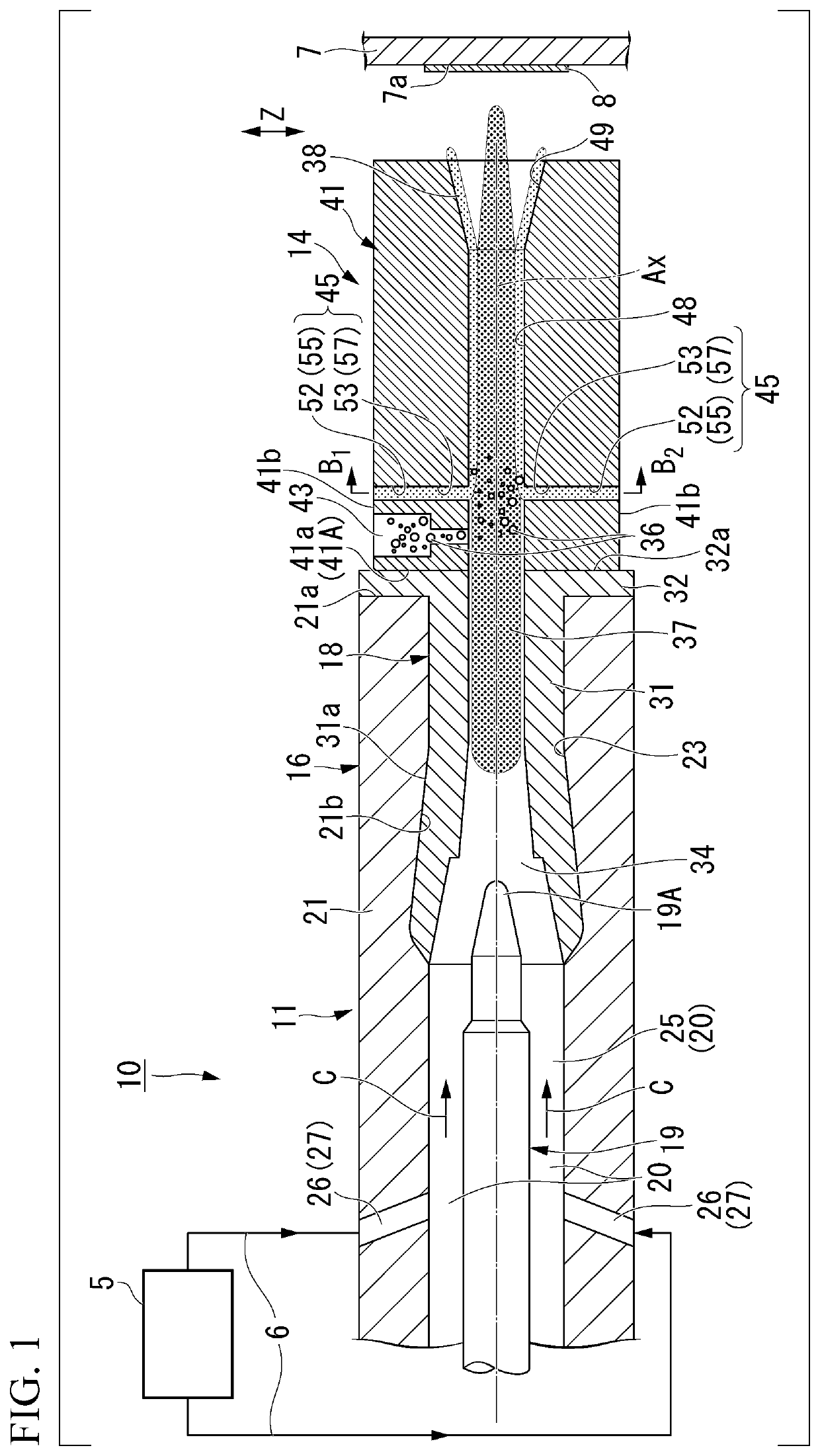
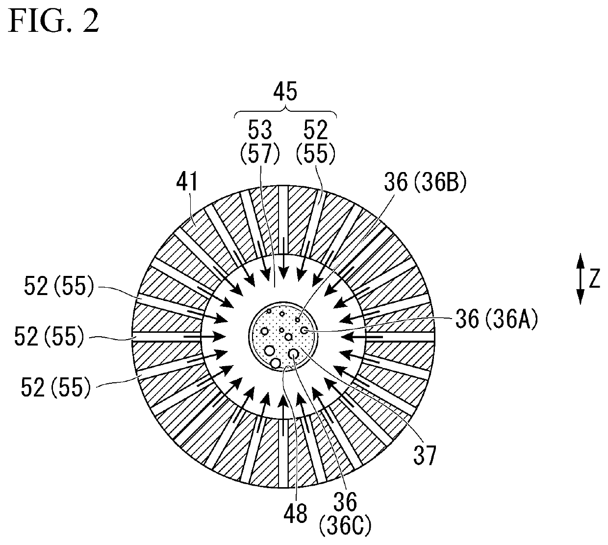
[0059]A plasma thermal spray device 10 of a first embodiment will be described with reference to FIGS. 1 and 2.

[0060]In FIG. 1, components other than a gas supply source 5, a gas supply line 6, and a cathode electrode 19 are illustrated in a section. In FIG. 1, Ax indicates an axis (hereinafter referred to as an “axis Ax”) of a plasma generation mechanism 11 and a thermal spray nozzle 14, C indicates a direction (hereinafter referred to as a “C direction”) in which a gas supplied through a gas introduction part 26 flows, and a Z direction indicates one direction of directions perpendicular to a plasma flame 37.

[0061]The plasma thermal spray device 10 has the plasma generation mechanism 11 and the thermal spray nozzle 14.

[0062]The plasma generation mechanism 11 has an electrode housing part 16, an anode electrode 18 (positive electrode), a cathode electrode 19 (negative electrode), and a second flow passage 20.

[0063]The electrode housing part 16 has an electrode housing part body 21,...

second embodiment

[0132]A plasma thermal spray device 70 according to a second embodiment of the invention will be described with reference to FIGS. 5 and 6. In FIG. 5, the same components as those of the structural body illustrated in FIG. 1 will be designated by the same reference signs.

[0133]In FIG. 6, illustration of the plasma flame 37 illustrated in FIG. 5 and the thermal spray powder 36A to 36C is omitted. An X direction illustrated in FIG. 6 indicates a direction orthogonal to the Z direction and the axis Ax. In FIG. 6, the same components as those of the structural body illustrated in FIG. 5 will be designated by the same reference signs.

[0134]The plasma thermal spray device 70 is configured similarly to the plasma thermal spray device 10 except for having a thermal spray nozzle 71 instead of the thermal spray nozzle 14 that constitutes the plasma thermal spray device 10 of the first embodiment.

[0135]The thermal spray nozzle 71 is configured similarly to the thermal spray nozzle 14 except fo...


PUM

PropertyMeasurementUnit
Currentaaaaaaaaaa
Diameteraaaaaaaaaa
Particle size distributionaaaaaaaaaa

Abstract

A plasma thermal spray device includes a nozzle body (41) having a main flow passage (48) that has a plasma flame (37) formed therein in a direction toward a downstream side from an upstream end (41A) disposed on one side in an axis direction, and extending along an axis (Ax); a powder introduction port (43) that is provided in a portion of the nozzle body (41) located the downstream side from the upstream end (41A) and introduces thermal spray powder (36) from a radially outer side to the plasma flame (37); and a fluid introduction port (45) that is provided at a position closer to the downstream side than a formation position of the powder introduction port (43) in the nozzle body (41) and introduces a working fluid into the main flow passage (48) from the radially outer side of the nozzle body (41).

Description

TECHNICAL FIELD[0001]The present invention relates to a thermal spray nozzle and a plasma thermal spray device.[0002]Priority is claimed on Japanese Patent Application No. 2017-188771, filed Sep. 28, 2017, the content of which is incorporated herein by reference.BACKGROUND ART[0003]As a conventional thermal spray device, there is a plasma thermal spray device that uses thermal spray powder.[0004]In the plasma thermal spray device, a working gas is converted into plasma by an arc generated between an anode and a cathode, and a plasma flame is formed with the working gas converted into the plasma.[0005]Then, a thermal spray film is formed by melting the thermal spray powder with the plasma flame and spraying the melted thermal spray powder on an object to be treated.[0006]The plasma thermal spray device having such a configuration is used, for example, when forming a thermal barrier coating film or an antifriction coating film on a gas turbine or an aircraft engine component.[0007]Gen...

Claims


Application Information

Patent Timeline
IPC IPC(8): C23C4/134
CPCC23C4/134B05B7/22B05B7/1463B05B7/1606B05B7/20B05C9/14B05C11/1042B05C19/008B05D1/08C23C24/08C23C4/129F05D2230/311
Inventor YOSHIDA, KAZUHIROFUKAO, SHINJIHIGASHI, KEITANIGAWA, SHUJIBONO, TAKUMI
Owner MITSUBISHI HEAVY IND LTD
Why Eureka
Try Eureka