Eureka AIR delivers breakthrough ideas for toughest innovation challenges, trusted by R&D personnel around the world.

Optically controlled millimeter-wave switch based on substrate integrated waveguide

Active Publication Date: 2021-03-25
SAMSUNG ELECTRONICS CO LTD
View PDF0 Cites 0 Cited by
  • Summary
  • Abstract
  • Description
  • Claims
  • Application Information

AI Technical Summary

Benefits of technology

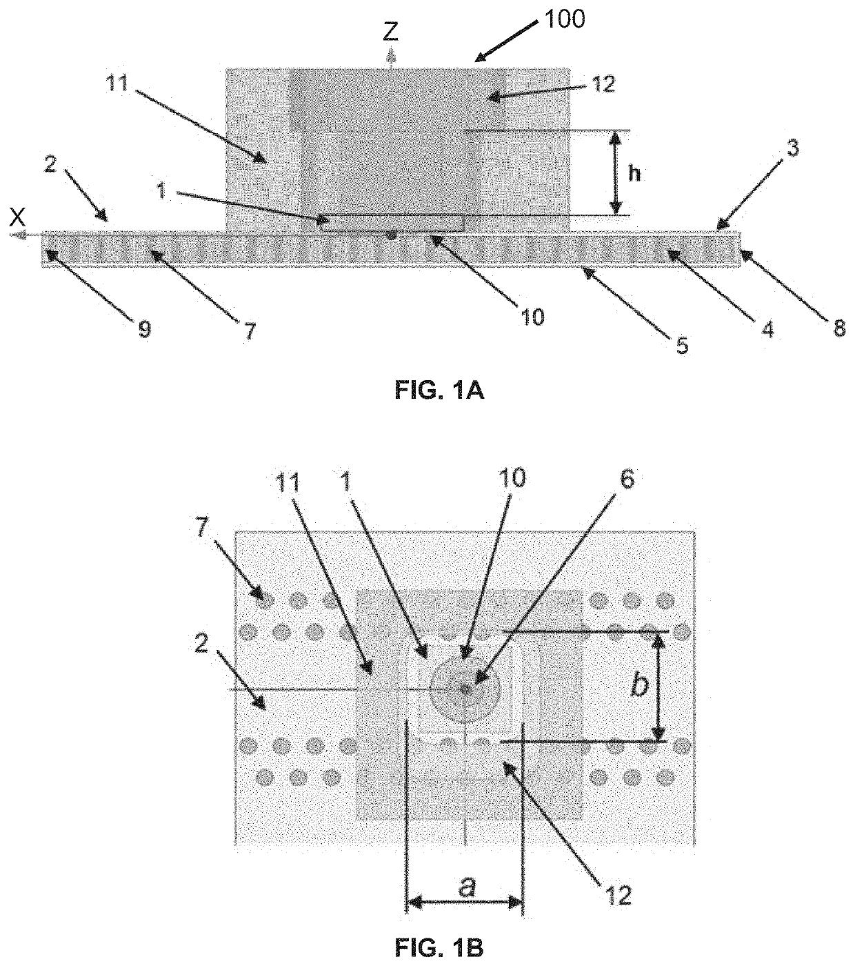
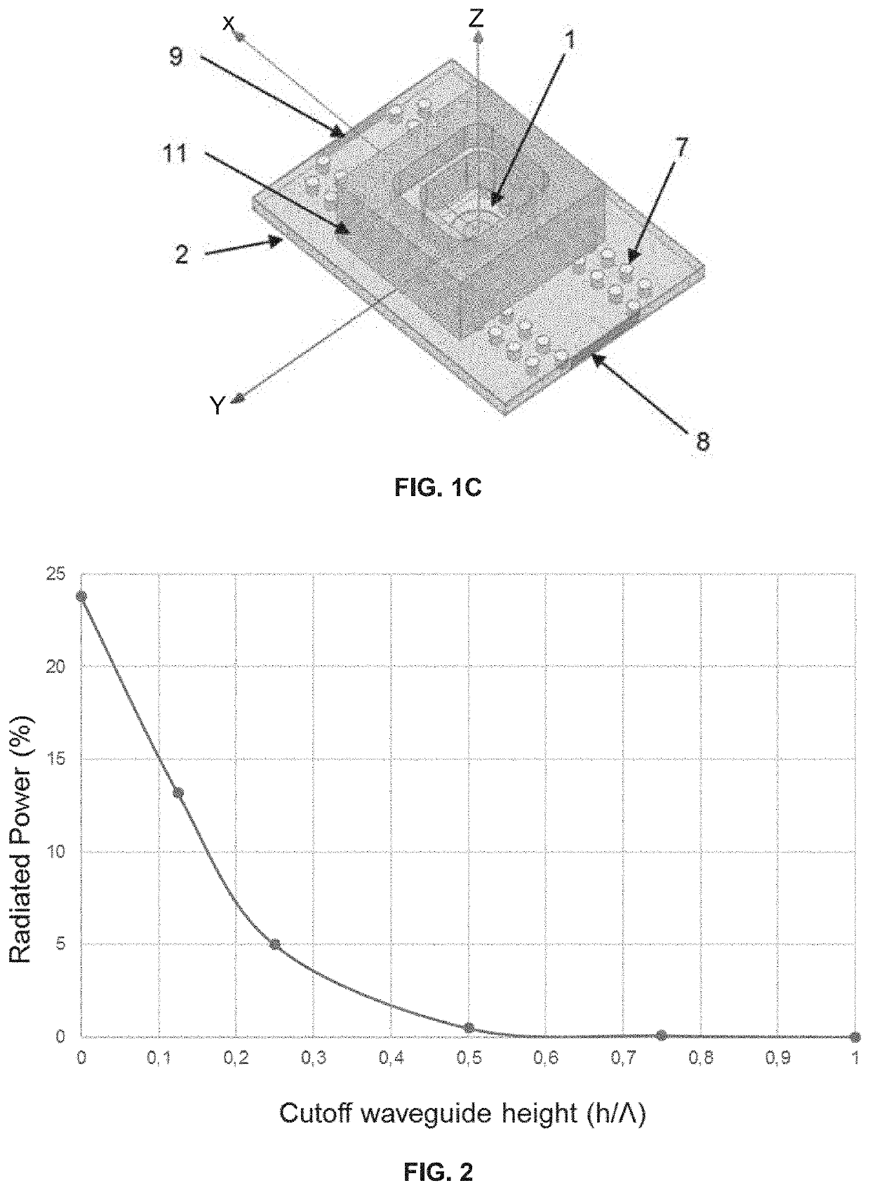
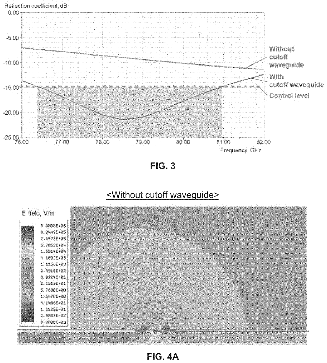
The patent describes an optically controlled switch that can control the transmission of electromagnetic waves. It includes a substrate integrated waveguide (SIW) with a photoconductive element and a cutoff waveguide. The cutoff waveguide is designed to provide control of the photoconductive element and block parasitic radiation. The cutoff waveguide has a cross-section in the form of a rectangle or circle and is filled with air or a dielectric material. The switch also includes an optically transparent element and a light source. The technical effects of this design include improved control of the photoconductive element, reduced parasitic radiation, and improved performance of the switch.

Problems solved by technology

At frequencies above 30 GHz, technological features of the device implementation have a great importance, because the wavelengths of the propagating waves are very small, and any discontinuity in propagation paths, which would not be significant for lower frequencies, may lead to parasitic and noise effects.
Accordingly, conventional switches for lower frequencies become inappropriate for high frequencies due to high losses.
As a result, losses are increased, matching in the RF path in an open state is degraded, external crosstalk is increased, ON / OFF isolation is degraded, and increased optical power is required from a control light source.
The heat produced by such increased optical power reduces its working life.

Method used


Image

  • Optically controlled millimeter-wave switch based on substrate integrated waveguide
  • Optically controlled millimeter-wave switch based on substrate integrated waveguide
  • Optically controlled millimeter-wave switch based on substrate integrated waveguide

Examples


Embodiment Construction

[0036]The following detailed description is provided to assist the reader in gaining a comprehensive understanding of the methods, apparatuses, and / or systems described herein. However, various changes, modifications, and equivalents of the methods, apparatuses, and / or systems described herein will be apparent after an understanding of the disclosure of this application. For example, the sequences of operations described herein are merely examples, and are not limited to those set forth herein, but may be changed as will be apparent after an understanding of the disclosure of this application, with the exception of operations necessarily occurring in a certain order. Also, descriptions of features that are known in the art may be omitted for increased clarity and conciseness.

[0037]The features described herein may be embodied in different forms, and are not to be construed as being limited to the examples described herein. Rather, the examples described herein have been provided mer...


PUM


Abstract

An optically controlled switch includes a substrate integrated waveguide (SIW) including: a first port and a second port, the first port and the second port being located at ends of the SIW to input and output an electromagnetic wave; and a shorting via electrically connected to a bottom layer of the SIW and separated from a top layer of the SIW by a dielectric gap. The optically controlled switch includes: a photoconductive element located on the top layer of the SIW and electrically connected to the shorting via and the top layer of the SIW, the photoconductive element being configured to have a dielectric state and a conductor state depending on a state of a controlling light flux; and a cutoff waveguide formed around the dielectric gap and the photoconductive element, and configured to provide control of the photoconductive element from a light source and block parasitic radiation.

Description

CROSS-REFERENCE TO RELATED APPLICATIONS[0001]This application claims the benefit under 35 USC § 119(a) of Russian Patent Application No. 2019130008 filed on Sep. 24, 2019 in the Russian Patent Office, and Korean Patent Application No. 10-2020-0100414 filed on Aug. 11, 2020 in the Korean Intellectual Property Office, the entire disclosures of which are incorporated herein by reference for all purposes.BACKGROUND1. Field[0002]The following description relates to radio engineering, and, for example, an optically controlled millimeter-wave switch based on a substrate integrated waveguide (SIW).2. Description of Related Art[0003]Currently, millimeter-wave networks and devices, such as 5G and 6G, WiGig, automotive radars, and the like, are being developed. The appearance of such new applications in the millimeter-wave range for frequencies above 30 GHz requires the development of a new class of elements and circuits (active elements, antennas, printed circuit boards (PCBs), feeders, and s...

Claims


Application Information

Patent Timeline
IPC IPC(8): H01L31/0232H01L31/16G02B6/42G02B6/28H01L27/144
CPCH01L31/02327H01L31/16H01L27/144G02B6/2861G02B6/4295H01L31/09H01L31/02325H01L31/0203H01P1/10
Inventor MAKURIN, MIKHAIL NIKOLAEVICHEVTYUSHKIN, GENNADIY ALEXANDROVICHLUKYANOV, ANTON SERGEEVICHNIKISHOV, ARTEM YURIEVICHSHEPELEVA, ELENA ALEKSANDROVNA
Owner SAMSUNG ELECTRONICS CO LTD
Why Eureka
Eureka Blog
Learn More