
Molded power module with integrated exciter circuit

Pending Publication Date: 2021-03-25
AUDI AG
View PDF6 Cites 1 Cited by
  • Summary
  • Abstract
  • Description
  • Claims
  • Application Information

AI Technical Summary

Benefits of technology

The technical effect of this patent is to provide a device that can better cool an exciter circuit and accurately measure electrical current.

Problems solved by technology

However, this current measurement means an increased expenditure for circuit board surface, for packaging of integrated circuits and for development.
In addition, the current measurement is more susceptible to faults and less robust.
A temperature drift of the current measurement (shunt) is also problematic.
A discrete structure of the exciter circuit results in varying shunt temperatures and thus in deviations in current measurement.

Method used


Image

  • Molded power module with integrated exciter circuit
  • Molded power module with integrated exciter circuit
  • Molded power module with integrated exciter circuit

Examples


Embodiment Construction

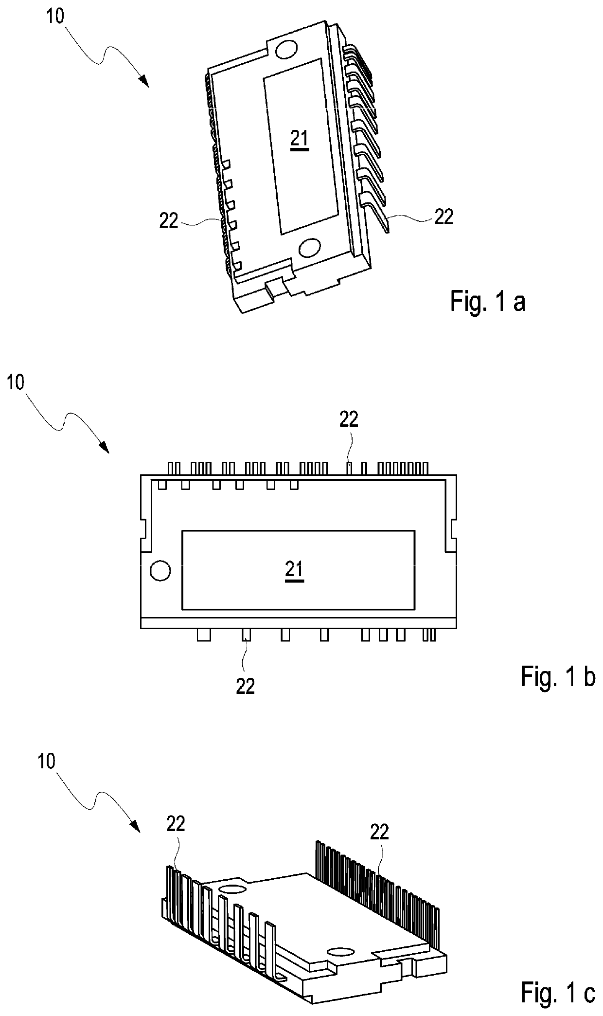
[0039]FIG. 1 shows a perspective top view of an embodiment of an inventive milled power module 10. The molded power module 10 comprises an exciter circuit (not shown) and a current sensor system (not shown). The molded power module 10 comprises pins 22 configured to establish an electrical connection to an internal interconnection (not shown). FIG. 1a shows that the power module 10 has a contact region 21 which is configured to be able to be placed on a main cooler (not shown) of a traction inverter.

[0040]FIG. 1b shows a top view of the embodiment of the power module 10 shown in FIG. 1a. The pins 22 and the contact region 21 are shown.

[0041]FIG. 1c shows a perspective side view of the embodiment of the power module 10 shown in FIGS. 1a and 1b. Pins 22 are shown, which are arranged in the direction of a PCB or circuit board (not shown) and pointing to an internal interconnection.

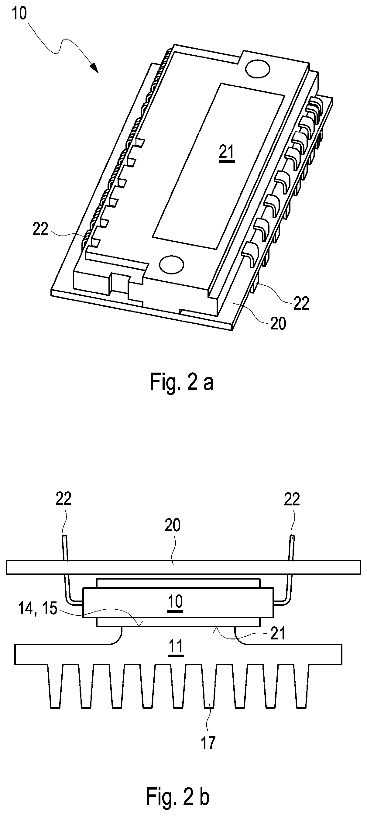
[0042]FIG. 2a shows a perspective side view of an embodiment of the power module 10 on a PCB 20 or circuit...


PUM


Abstract

A power module for electric drives is provided which comprises at least one exciter circuit with at least one power semiconductor, wherein the power module is molded and the exciter circuit with the at least one power semiconductor is integrated in the molded power module. A traction inverter is also provided which comprises a water-cooled main cooler, wherein the main cooler comprises a bearing surface which is configured to receive power modules, wherein the traction inverter comprises at least one molded power module, and wherein the main cooler forms a cooling connection which is configured to receive the molded power module on the main cooler.

Description

BACKGROUNDTechnical Field[0001]Embodiments of the present invention relate to a power module for electric drives and to a traction inverter comprising a power module.Description of the Related Art[0002]Such power electronics are normally used to drive a 3-phase electric machine for traction drives (EV, HEV of the PHEVs). A special embodiment of the electric machine is the so-called separately excited synchronous machine. In contrast to the permanently excited synchronous machine, this type of machine manages without magnetic materials on a rotor and generates the rotor magnetic field by means of an energized winding in the rotor. This introduces additional degrees of freedom in the control and design of the electric machine, whereby increases in efficiency and performance can be achieved.[0003]According to the current prior art, the current is supplied to a rotor winding via slip ring contacts. Excitation of the rotor winding must be effected by means of an additional power electron...

Claims


Application Information

Patent Timeline
IPC IPC(8): H05K7/20H01L23/31H01L23/36H05K7/14H02M1/32
CPCH05K7/20945H01L23/31H01L23/36H02M2001/327H05K7/1432H02M1/32H05K7/209H02M1/00H02M7/003H05K7/20927H01L23/4334H01L23/473H01L23/3107H05K7/14322H02M1/327H05K7/20254
Inventor RUPPERT, DANIEL
Owner AUDI AG
Learn More