Electro-fuel energy storage system and method

a technology of energy storage system and electro-fuel, which is applied in the direction of fuel cells, electrochemical generators, cell components, etc., can solve the problems of poor scalability, implementation of large-scale energy storage applications, and intermittent electricity generated from these power sources, and achieve high flexibility in selecting, and high energy efficiency.

Active Publication Date: 2021-04-08
THE HONG KONG UNIV OF SCI & TECH
View PDF0 Cites 0 Cited by
  • Summary
  • Abstract
  • Description
  • Claims
  • Application Information

AI Technical Summary

Benefits of technology

[0015]2. The e-fuel energy storage system of this invention has high flexibility in selecting and preparing electro-active materials. Redox species in the conventional flow batteries cannot simultaneously meet the property of reversibility and other requirements such as power density, energy efficiency, cell potential, cost, and stability. In this invention, the e-fuel charger and e-fuel cell are independent. This feature allows both the e-fuel charger and e-fuel cell to be designed and optimized in accordance not only with their component (e.g. electrode, membrane), material and design but also with individual performance targets, eliminating the conflicts between charge and discharge processes, and there is a high flexibility in selecting and creating electro-active materials as e-fuels. The e-fuel charger can store intermittent energy generated from solar cells or wind turbines, then release electricity through the e-fuel cell whenever and wherever needed to meet the requirements of the grid system and off-grid systems. The energy density of the e-fuel storage system of this invention can be as high as 150-300 Wh/L. Its energy efficiency can be higher than 80% (the energy efficiency of the state-of-the-art hydrogen storage system is about 50%). The capital cost of the system can meet the target set by the United States Department of Energy (DOE) (250 $/kWh).
[0016]Unlike conventional batteries which constrain the two reactions to the same electrode surface, the e-fuel system of this invention separates the reduction and oxidation reactions onto two electrodes that can be designed and optimized to maximize the kinetics of the two reactions, respectively. For instance, the lead catalyst cannot be used in the electrode of iron-chromium redox flow batteries because it is unstable during the discharge process. The sluggish kinetics of chromium re...

Problems solved by technology

Energy shortage and climate change are among the major problems in the world today.
However, the electricity generated from these power sources are intermittent and fluctuant, and thus unreliable.
Although solid-state batteries have been widely used in the small-scale energy storage, there are still some difficulties in implementing applications in large-scale energy storage due to some technical, economic, and safety issues such as poor scalability, high cos...

Method used


Image

  • Electro-fuel energy storage system and method
  • Electro-fuel energy storage system and method
  • Electro-fuel energy storage system and method

Examples


Embodiment Construction

[0029]In order to facilitate the understanding of this invention, the present invention will be described more comprehensively. However, the invention can be embodied in many different forms and is not limited to the examples described herein. Rather, these examples provided the aim to make a more thorough and comprehensive understanding of this invention.

[0030]Unless defined, all technical and scientific terms used herein have the same meaning as commonly understood by one of ordinary skills in the art to which this invention belongs. The terminology used in the description of the present invention is to describe particular examples and is not intended to limit the invention. The term “and / or” as used herein includes any and all combinations of one or more of the associated listed items.

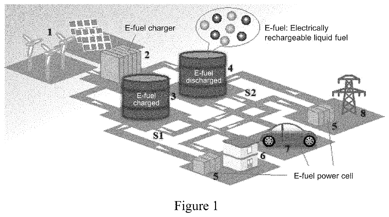
[0031]The e-fuel energy storage system and methods of this invention comprise an electroactive liquid fuel (e-fuel) which can be charged and discharged repeatedly. The electric energy generated by t...


PUM


Abstract

An e-fuel energy storage system and method are provided. The e-fuel energy storage system comprises e-fuel6an e-fuel charger, and an e-fuel cell, wherein the component such as an electrode and membranes, material, and design configured to charge the e-fuel are independent and different from the component such as an electrode and membranes, material, and design configured to discharge the e-fuel.

Description

CROSS-REFERENCE TO RELATED APPLICATIONS[0001]This application is the U.S. national stage application of International Patent Application No. PCT / CN2018 / 078827, filed Mar. 13, 2018, which claims the benefit under 35 U.S.C. § 119 of Chinese Application No. 201710150419.9, filed Mar. 14, 2017, the disclosures of each of which are incorporated herein by reference in their entirety.TECHNICAL FIELD[0002]This invention relates to the field of energy storage technologies, and in particular, to an e-fuel energy storage system and method.BACKGROUD OF THE INVENTION[0003]Energy shortage and climate change are among the major problems in the world today. An effective way to solve these problems is by increasing the proportion of renewable energy to solve energy and environmental problems. Solar energy and wind energy are two of the largest sustainable sources of carbon-free power, and remarkable progress in both solar photovoltaics (PVs) and wind turbines has been achieved in the past decades. H...

Claims


Application Information

Patent Timeline
IPC IPC(8): H01M8/18H01M8/04082
CPCH01M8/188H01M8/04216H01M8/06H01M8/184Y02E60/50H01M8/04201H01M8/0656H01M4/926H01M4/96H01M4/9016H01M8/103
Inventor ZHAO, TIANSHOU
Owner THE HONG KONG UNIV OF SCI & TECH
Why Eureka
Try Eureka