
Gas-liquid mixing control system and control method for gas-liquid mixing

Pending Publication Date: 2021-04-15
TRUSVAL TECH
View PDF0 Cites 0 Cited by
  • Summary
  • Abstract
  • Description
  • Claims
  • Application Information

AI Technical Summary

Benefits of technology

The present invention provides a gas-liquid mixing control system and method that regulates the output flow of gas-liquid mixed fluid in a non-electric way and can supply flow in a large range (2~16 LPM). This allows a single gas-liquid mixing control system to meet the flow requirements for both low-flow (2~4 LPM) and high-flow (10~14 LPM). The gas-liquid mixing control system and method work in a non-electric way, which avoids the consumption of power resources and meets the environmental protection requirements of the new-type manufacturing industry.

Problems solved by technology

Therefore, conventional control method for gas-liquid mixed fluid needs electric control devices, which causes a great consumption of electric power and becomes a problem of environmental protection.
Moreover, in the above-mentioned control method, the flow of the gas-liquid mixed fluid that the electric control device can supply is subject to restriction (e.g., 6˜8 LPM).
However, connecting multiple control units in parallel occupies additional space in the plant and consumes a large amount of electric power, which increases the manufacturing cost of the above-mentioned high-tech product parts.
On the other hand, if the flow of the gas-liquid mixed fluid required by the manufacturing machine is low (e.g., 2˜4 LPM), which exceeds the control capability of the electric control devices, concentration ratio and other related parameters of the gas-liquid mixed fluid will be imbalanced, so that the requirements of the above-mentioned manufacturing machine will not be satisfied.
It is known from the above that there are many problems in the existing gas-liquid mixing control system and control method, which still needs to be improved, BRIEF SUMMARY OF THE INVENTION

Method used


Image

  • Gas-liquid mixing control system and control method for gas-liquid mixing
  • Gas-liquid mixing control system and control method for gas-liquid mixing
  • Gas-liquid mixing control system and control method for gas-liquid mixing

Examples


Embodiment Construction

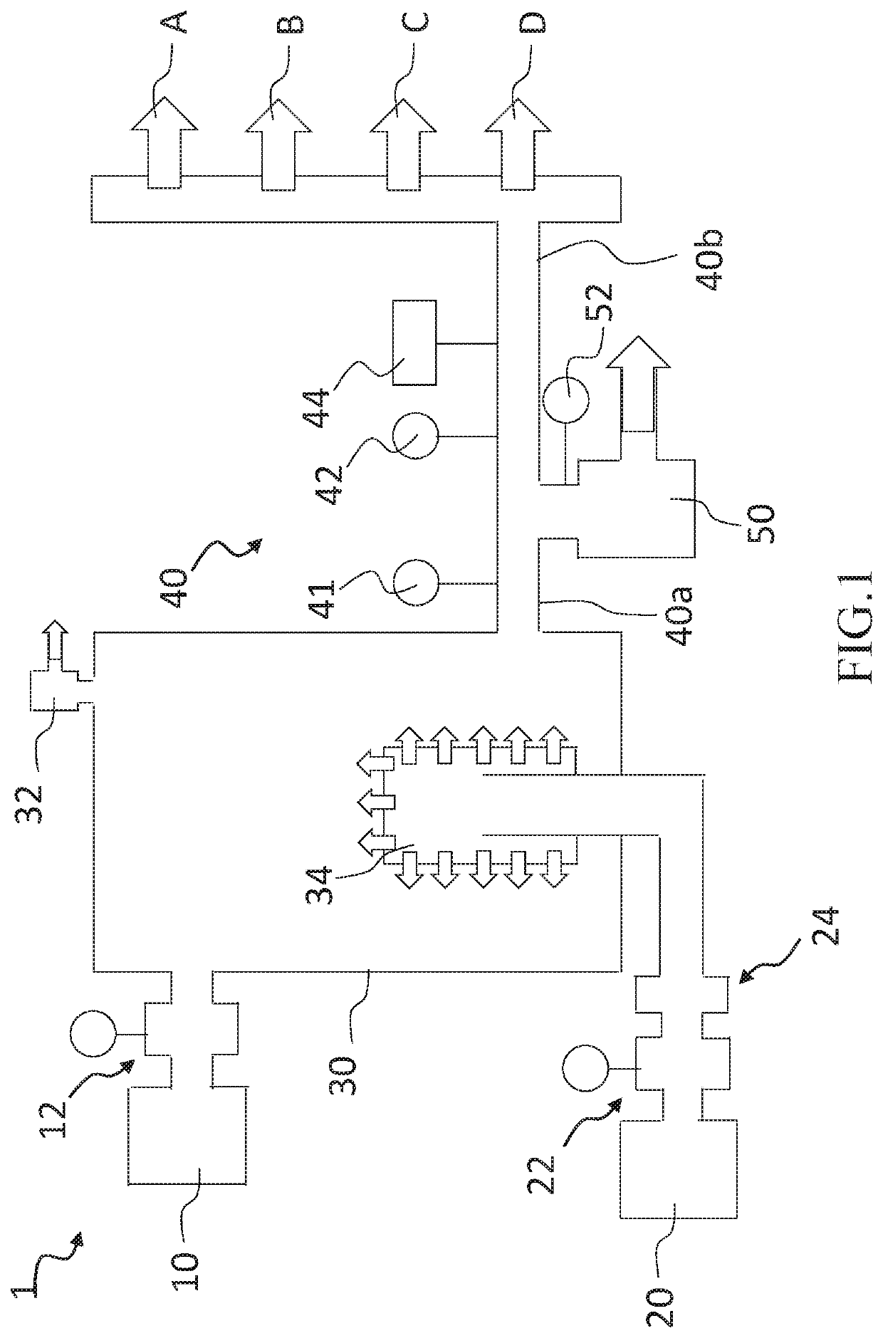
[0020]FIG. 1 is a schematic diagram of a gas-liquid mixing control system 1 of a preferred embodiment of the present invention. The gas-liquid mixing control system 1 can be used to mix water and carbon dioxide to form carbon dioxide water fluid, but this is not a limitation of the present invention. Chemical liquid dilution system 1 includes a liquid supply unit 10, a gas supply unit 20, a mixing tank 30, an output pipe 40, and a non-electric control flow regulator 50.

[0021]In this embodiment, the liquid supply unit 10 is used to provide a liquid with a first constant pressure and a first flow (such as water), and the gas supply unit 20 is used to provide a gas with a second constant pressure and a second flow (such as carbon dioxide).

[0022]In FIG. 1. the mixing tank 30 is connected to the liquid supply unit 10 and the gas supply unit 20. Moreover, the liquid supply unit 10 inputs the liquid into the mixing tank 30 with the first constant pressure and the first flow. A liquid press...


PUM

PropertyMeasurementUnit
Pressureaaaaaaaaaa
Electrical conductivityaaaaaaaaaa
Poweraaaaaaaaaa

Abstract

A gas-liquid mixing control system includes a liquid supply unit, a liquid pressure regulating valve, a gas supply unit, a gas pressure regulating valve, a mixing tank, an output pipe, and a non-electric control flow regulator. The mixing tank communicates with said regulating valves; liquid and gas are mixed in the mixing tank to form mixed fluid. The first end and second end of output pipe communicate with the mixing tank and the machine respectively, making mixed fluid output from mixing tank to machine through the output pipe. The mixed fluid in first end and second end have third flow and fourth flow respectively. Said flow regulator communicates with the output pipe; the mixed fluid passing through said flow regulator has fifth flow. The first flow is not lower than at least one of the fourth and the fifth flow. Additionally, a control method for gas-liquid mixing is disclosed.

Description

BACKGROUND OF THE INVENTION1. Technical Field[0001]The present invention relates generally to a gas-liquid mixing system, and more particularly to a gas-liquid mixing control system and a control method for gas-liquid mixing.2. Description of Related Art[0002]In the high-tech field, gas-liquid mixed fluid with stable concentration is required to manufacture high-tech product parts (e.g., semiconductor chips, display devices, touch panels). Such gas-liquid mixed fluid with stable concentration is usually supplied to a manufacturing machine for the above-mentioned high-tech product parts at a constant pressure and flow.[0003]Generally, an electric control device (such as a mass-flow controller, MFC) is used adjust the pressure and flow of the liquid and gas input to the mixing tank for forming the gas-liquid mixed fluid. Furthermore, another electric control device is used to adjust the pressure and flow of the gas-liquid mixed fluid output to the manufacturing machine. Therefore, con...

Claims


Application Information

Patent Timeline
IPC IPC(8): B01F15/00B01F3/04B01F15/02
CPCB01F15/00253B01F15/0261B01F15/0037B01F3/04255B01F23/2312B01F23/23762B01F35/2213B01F35/2209B01F23/23122B01F35/22141B01F35/718051
Inventor CHIEN, SHIH-PAOCHEN, CHENG-HSUNCHOU, KUAN-HUNGSU, YI-SENGUO, JHE-WEI
Owner TRUSVAL TECH
Features
  • Generate Ideas
  • Intellectual Property
  • Life Sciences
  • Materials
  • Tech Scout
  • Unparalleled Data Quality
  • Higher Quality Content
  • 60% Fewer Hallucinations
Learn More