Position monitoring of a gasket between tunnel segments

a technology of gasket and tunnel segment, which is applied in the direction of tunnel lining, mining devices, instruments, etc., can solve problems such as detrimental leakage, and achieve the effects of reducing sensor calibration efforts, limiting the amount of power required, and constant temperature reading of the temperature sensor

Pending Publication Date: 2021-04-15
FNV IP BV
View PDF16 Cites 0 Cited by
  • Summary
  • Abstract
  • Description
  • Claims
  • Application Information

AI Technical Summary

Benefits of technology

[0039]The temperature control function implemented in the software of the controller adjusts the amount of heating power continuously, in order to maintain a constant temperature reading of the temperature sensor. The temperature-vs-distance calibration can thus be limited to the single reference temperature that has been chosen, and significantly reduces sensor calibration efforts.
[0040]In a further embodiment, the sensor system includes a substrate, for instance a printed circuit board (PCB), which defines a first surface on which the sensor is arranged. The substrate includes cut-outs that extend from the first surface, entirely through the substrate, and to a second surface of the substrate being opposite to the first surface. The cut-outs extend around and enclose a partly isolated portion of the substrate where the sensor is located. These cut-outs are mutually separated by bridge portions, which mechanically connect the partly isolated portion to a remainder of the substrate that surrounds the cut-outs and the partly isolated portion. The cut-outs help to thermally insulate the sensor (for measuring gasket position indication) from the surrounding substrate, and limit the amount of power required to heat this sensor to this controlled and stable temperature.
[0041]In yet a further embodiment, the number of bridge portions equals three or four. Preferably, the bridge portions are arranged, viewed along the nominal plane of the substrate, in a regular (i.e. discrete rotationally symmetric and / or mirror symmetric) distribution around the partly isolated portion, in order to prevent mechanical displacement of the partly isolated portion relative to the remainder of the substrate.

Problems solved by technology

Gaskets that significantly deform due to hydrostatic pressure from the water and soil surrounding the structure may eventually result in detrimental leaks.

Method used


Image

  • Position monitoring of a gasket between tunnel segments
  • Position monitoring of a gasket between tunnel segments
  • Position monitoring of a gasket between tunnel segments

Examples


Embodiment Construction

lass="d_n">[0087]The following is a description of certain embodiments of the invention, given by way of example only and with reference to the figures.

[0088]The term “surface” is used herein to generally refer to a two-dimensional parametric surface region, which may have either an entirely or piece-wise flat shape (e.g. a plane or polygonal surface), a curved shape (e.g. cylindrical, spherical, parabolic surface, etc.), a recessed shape (e.g. stepped or undulated surface), or a more complex shape. The term “plane” is used herein to refer to a flat surface defined by three non-coinciding points.

[0089]The term “path” refers herein to a non-intersecting line trajectory that extends in three-dimensional space.

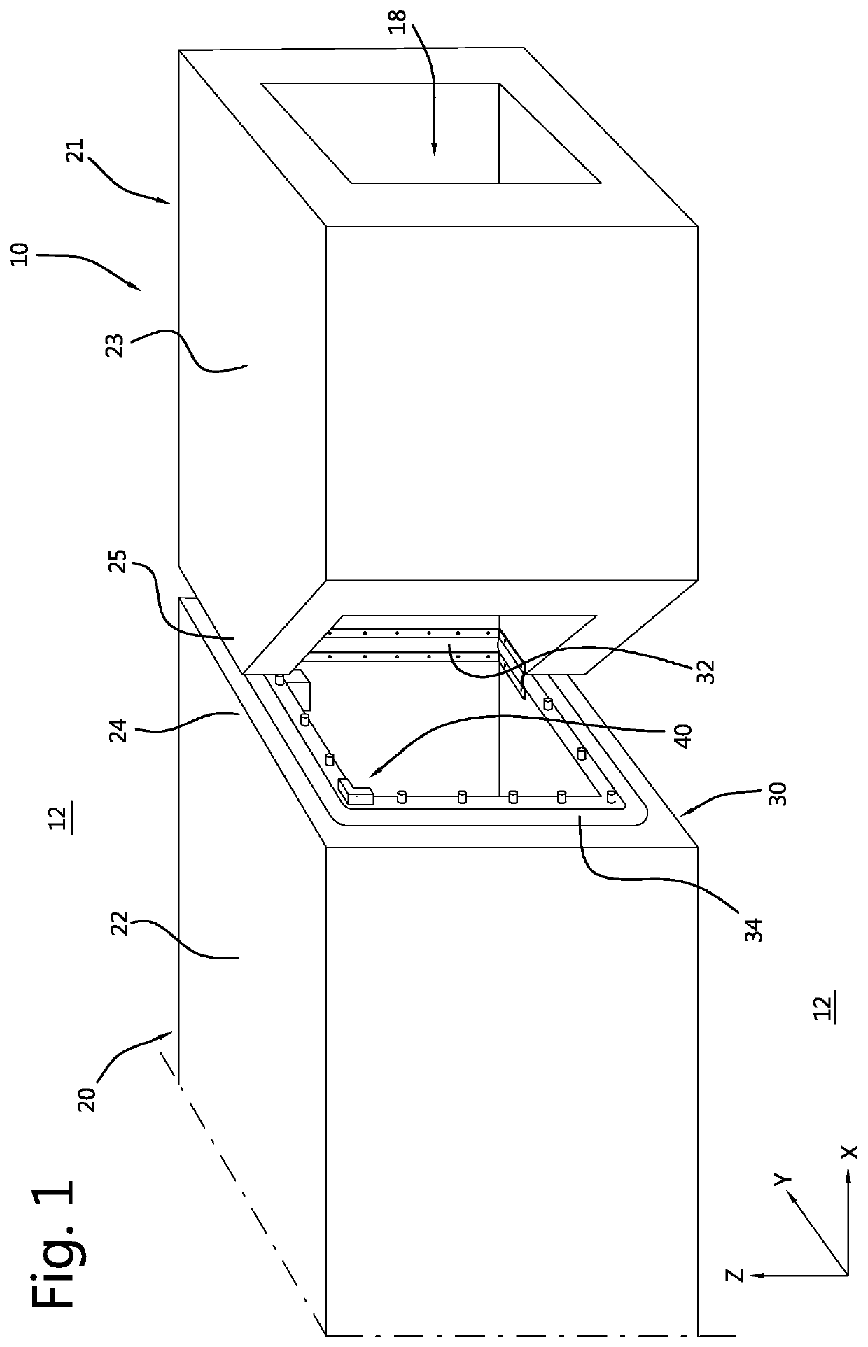
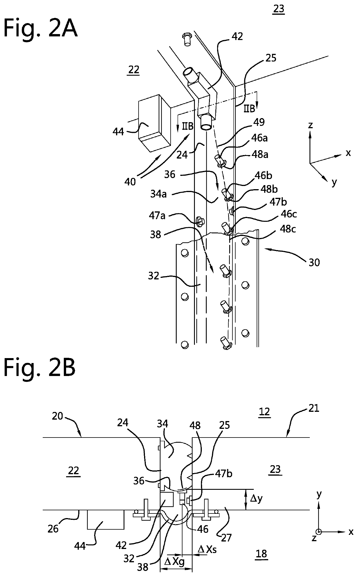
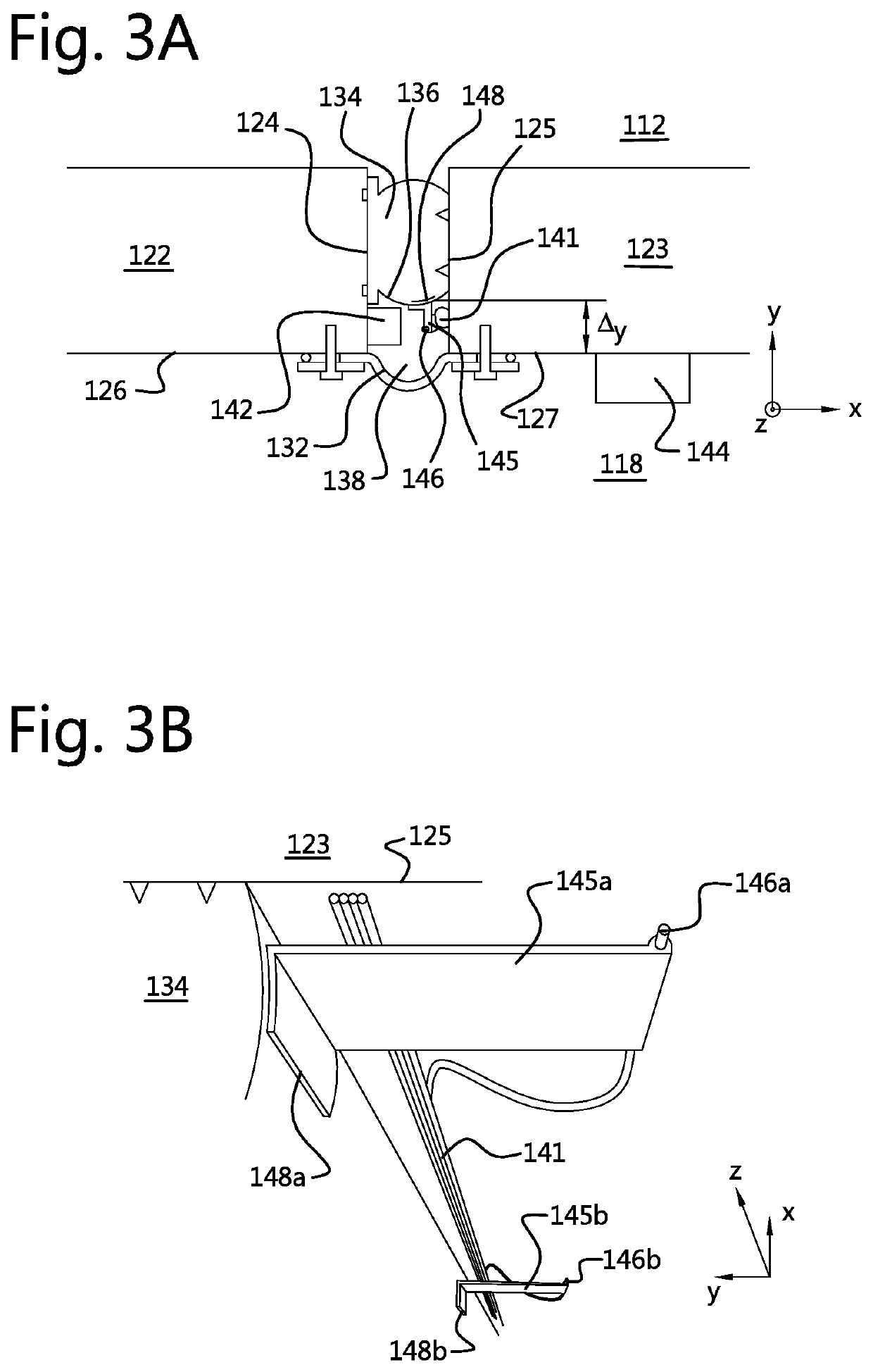
[0090]In the next figures, Cartesian coordinates will be used to describe spatial relations for exemplary embodiments of the sensor system. Reference symbol X is used to indicate a longitudinal direction, which is associated with a direction along the passage through the tunnel. ...


PUM


Abstract

A method and sensor system for monitoring in time a geometric property of a gasket (32, 34) that sealingly interconnects two structural members (20, 21) of a subterraneous or immersed tunnel (10). The system includes a sensor (42) for measuring position indications for surface portions (48) of the gasket relative to a reference (26, 27, 47) associated with one or both structural members, and a processor (44) that is coupled with the sensor to receive the position indications. The processor is configured to derive indications of displacement (ΔY) for each of the gasket surface portions based on the measured indications of position, to compare the indications of displacement for each of the gasket surface portions with at least one threshold value (Ty), and to generate a warning message for an operator if at least one of the indications of displacement transgresses the at least one threshold value.

Description

TECHNICAL FIELD[0001]The invention relates to monitoring in time a geometric property of a gasket in an at least partially subterraneous and / or immersed structure.BACKGROUND ART[0002]Tunnels typically form an important constituent of road and / or railway networks. A tunnel is typically formed of a plurality of rigid (e.g. concrete) tubular elements that are several tens to hundred meters long, and which have cylindrical or rectangular cross-sectional shapes. These tubular elements are connected along edges in longitudinal directions, to form a tunnel structure with an internal passageway for passing through traffic. For tunnels that are constructed below the soil and / or water level, the rigid tube elements should be interconnected by joints that include flexible gaskets for preventing the outside environment (water, sediment etc.) from entering into the tunnel. These gaskets may for instance include rubber gaskets as described in patent document WO2015 / 169707A2.[0003]Over time, the c...

Claims


Application Information

Patent Timeline
Patent Type & Authority Applications(United States)
IPC IPC(8): F16J15/06E21F17/18G01M13/005
CPCF16J15/064G01M13/005E21F17/18E21D11/385G01B11/002G01B11/27G01B9/00G01B11/272G01B11/16G01B11/022
Inventor JONGSMA, ARNOUD MARCVAN WEEREN, DENNIS
Owner FNV IP BV
Why Eureka
Try Eureka