
Decelerating clutch of a washing machine, and washing machine

a technology of decelerating clutch and washing machine, which is applied in the field of laundry equipment, can solve the problems of small resistance to axial load, large noise and vibration, and achieve the effects of reducing force, avoiding looseness or cracking of connecting points, and improving the capability of the output shaft sleev

Active Publication Date: 2021-04-29
QINGDAO HAIER WASHING ELECTRIC APPLIANCES CO LTD +1
View PDF0 Cites 1 Cited by
  • Summary
  • Abstract
  • Description
  • Claims
  • Application Information

AI Technical Summary

Benefits of technology

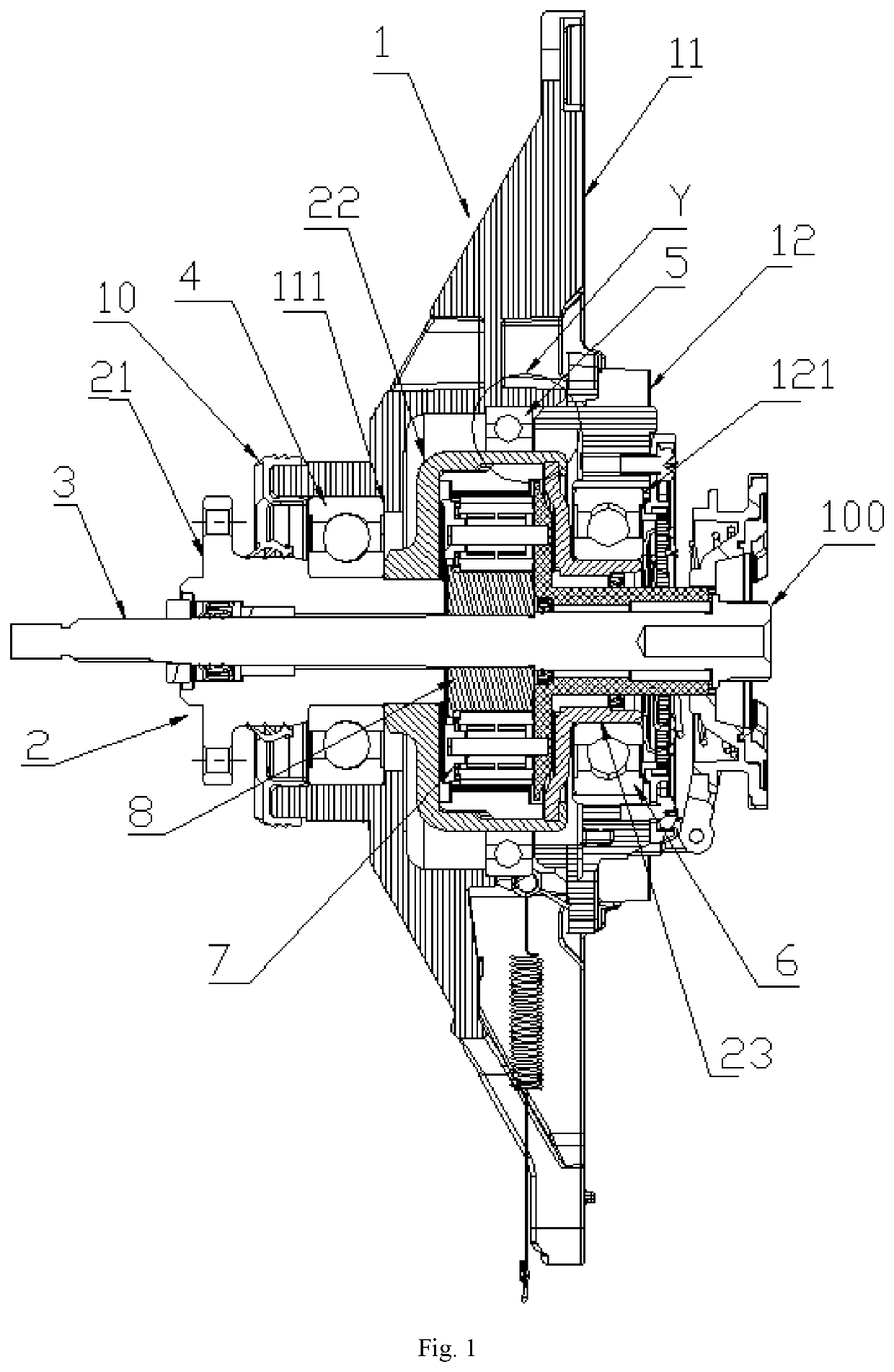
The present patent provides a decelerating clutch for a washing machine that improves the machine's ability to resist radial loads and decrease shaking during operation. By adding a bearing between the existing front and rear bearings, the added bearing supports a middle part of the output shaft sleeve, reducing the force on the connecting point between the brake wheel and the oil seal cover, avoiding damage and reducing the likelihood of collisions between the inner and outer barrels. The decelerating clutch of the present patent has a longer service life and lower maintenance cost, while also reducing noise during operation and improving the user experience.

Problems solved by technology

Through such a pressing rivet process, a greater axial load can be resisted after a brake wheel is connected with an oil seal cover; however, the capability in resisting against an axial load is small.
During operation of a washing machine, due to shaking of an inner barrel, a greater radial load will be exerted on a connecting point between a brake wheel and an oil seal cover, and the greater radial load easily causes looseness at a connecting point between the brake wheel and the oil seal cover, and further, shaking of an inner barrel is expanded, and finally, the inner barrel is in friction with an outer barrel, and problems of big noise and big vibration arise.

Method used


Image

  • Decelerating clutch of a washing machine, and washing machine
  • Decelerating clutch of a washing machine, and washing machine
  • Decelerating clutch of a washing machine, and washing machine

Examples


embodiment 1

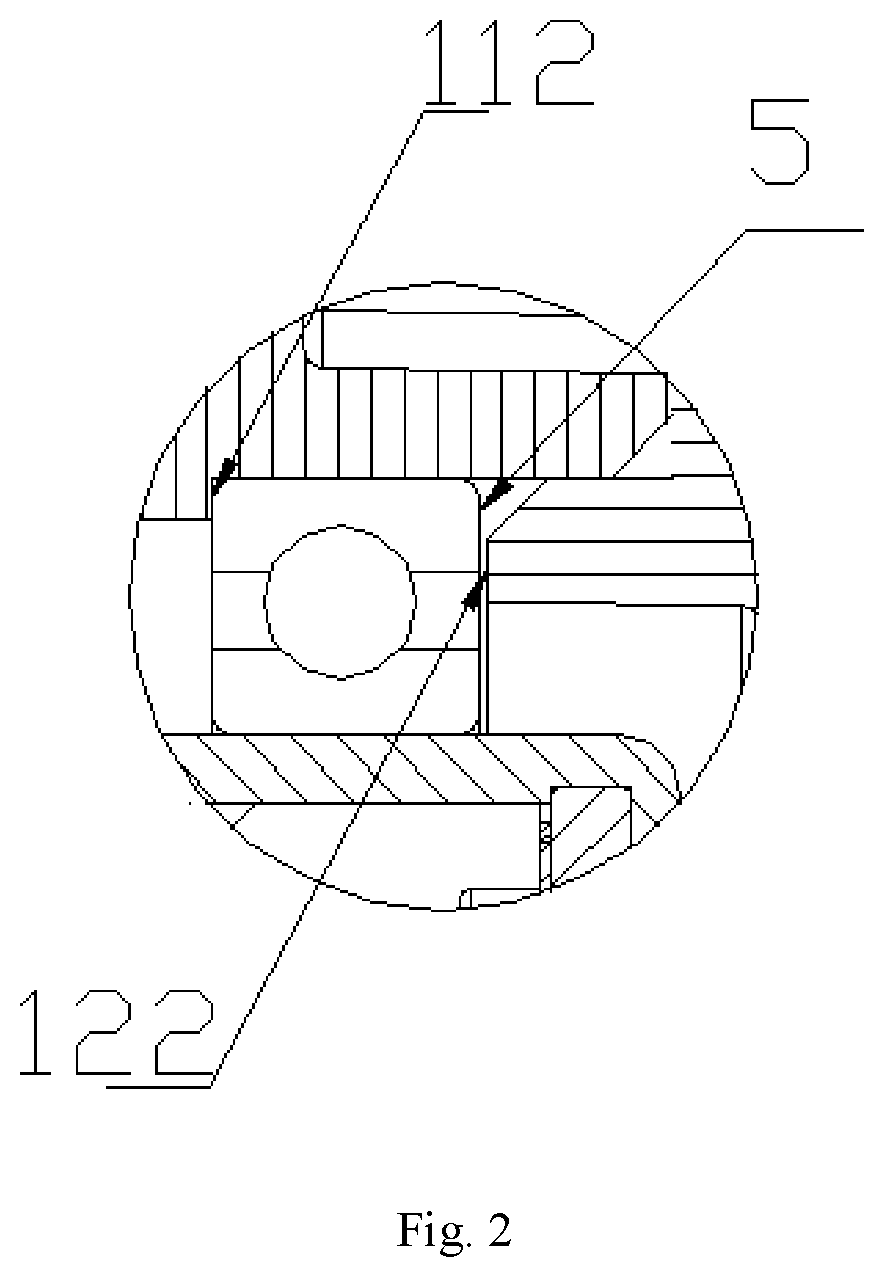
[0026]As shown in FIG. 1 and FIG. 2, a decelerating clutch of a washing machine includes a bearing seat 1, an input shaft 100, an output shaft 3, and an output shaft sleeve 2, wherein the input shaft 100 and the output shaft 3 are arranged coaxially, the output shaft sleeve 2 is sleeved on the input shaft 100 and the output shaft 3, the output shaft sleeve 2 can rotate relative to the input shaft 100, and the output shaft sleeve 2 is connected with the input shaft 100 in a transmission manner via a planetary gear train. Preferably, the input shaft 100 and the output shaft 3 are configured to a through-shaft, and they are of an integrated structure. The input shaft 100 is connected with a motor shaft, the output shaft 3 is connected with an impeller in an inner barrel, and the output shaft sleeve 2 is connected with an inner barrel to drive rotation of an inner barrel. The output shaft sleeve 2 is installed on a bearing seat 1 via a bearing, and can rotate relative to the bearing sea...

embodiment 2

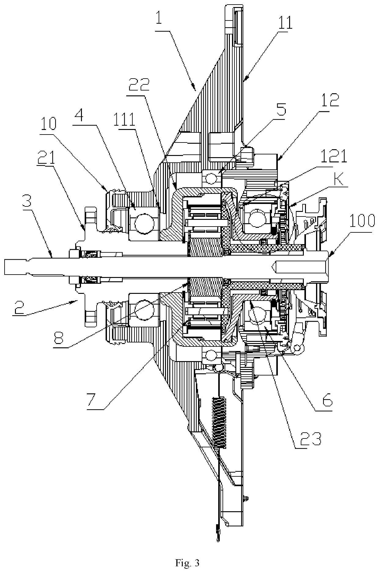
[0035]In embodiment 1, the output shaft sleeve 2 is not completely axially limited; therefore, the output shaft sleeve 2 may be enabled to move towards one side of an inner barrel. In combination with FIG. 3 and FIG. 4, the present embodiment differs from embodiment 1 as follows: the third locating surface 121 is arranged at one side, close to the brake wheel 22, of the third bearing 6, and limits movement of the third bearing 6 towards one side of an inner barrel. The oil seal cover 23 is clamped with a C-shaped check ring 9, and the C-shaped check ring 9 is arranged at another side of the third bearing 6 and is in location fit with the third bearing 6, to limit movement of the output shaft sleeve 2 towards one side of an inner barrel. When the output shaft sleeve 2 moves towards one side of a motor, the output shaft sleeve 2 will be limited by the first locating surface 111 on the first bearing seat 11, and when the output shaft sleeve 2 moves towards one side of an inner barrel, ...


PUM


Abstract

A decelerating clutch of a washing machine includes a bearing seat, an input shaft, an output shaft, and an output shaft sleeve. The input shaft and the output shaft are coaxial, the output shaft sleeve is sleeved on the input shaft and the output shaft, the output shaft sleeve is installed on the bearing seat via a bearing, the output shaft sleeve is connected with the input shaft via a planetary gear train, two ends and a middle part of the output shaft sleeve are respectively provided with at least one bearing, an inner ring of the bearing is coordinated with the output shaft sleeve, and an outer ring is coordinated with the bearing seat. The decelerating clutch of a washing machine improves a capability of an output shaft sleeve in resisting against a radial load, and further prolongs the service life of a decelerating clutch of a washing machine.

Description

TECHNICAL FIELD[0001]The present disclosure relates to laundry equipment, in particular to a decelerating clutch of a washing machine and a washing machine.BACKGROUND ART[0002]A decelerating clutch of an existing impeller-type washing machine is generally internally installed with two groups of bearings, which are respectively a front bearing arranged at one side of an inner barrel and a rear bearing arranged at one side of a motor, and the two bearings are jointly used for supporting an inner barrel shaft. A front end of a brake wheel is installed on an inner barrel shaft, and a rear end is fixed on an oil seal cover through a pressing rivet process. Through such a pressing rivet process, a greater axial load can be resisted after a brake wheel is connected with an oil seal cover; however, the capability in resisting against an axial load is small. During operation of a washing machine, due to shaking of an inner barrel, a greater radial load will be exerted on a connecting point b...

Claims


Application Information

Patent Timeline
Patent Type & Authority Applications(United States)
IPC IPC(8): D06F37/40D06F37/36D06F23/04F16C33/58
CPCD06F37/40D06F37/36F16C3/02F16C33/583D06F23/04D06F37/30F16C2314/00
Inventor CHI, ZONGRUILUAN, HOULI
Owner QINGDAO HAIER WASHING ELECTRIC APPLIANCES CO LTD
Learn More