
Radiant Conveyor Drying System and Method

Active Publication Date: 2021-04-29
WOOD WILLIAM J
View PDF0 Cites 2 Cited by
  • Summary
  • Abstract
  • Description
  • Claims
  • Application Information

AI Technical Summary

Benefits of technology

The patent describes a method of drying plant products using a conveyor system. The method involves positioning the plant product on the conveyor and directing radiant heat from a burning unit or heating element downward onto the plant product while convective air is produced using a fan or heat exchange system. This air flows downward around the plant product and helps to move the radiant heat through the plant product. The technical effect of this method is to provide a more efficient and effective method of drying plant products.

Problems solved by technology

Too little moisture results in a vulnerable plants prior to harvesting, and damage to product during storage due to brittleness.
Too much moisture may resulting in molding of product during storage.
However, stationary heating does not provide for a continuous operation.
The auger type systems does not provide for a controlled environment to ensure accurate drying of product.
However, these prior art operations position radiant heating elements either under the product of beside the product as the product moves along the conveyor.
The prior art orientation of the convection output and heating elements does not provide for an efficient distribution of the radiant heat produced.
However, none of these prior art product drying operations provides for a means to remove byproduct of the harvesting process amalgamated with the product.

Method used


Image

  • Radiant Conveyor Drying System and Method
  • Radiant Conveyor Drying System and Method
  • Radiant Conveyor Drying System and Method

Examples


first embodiment

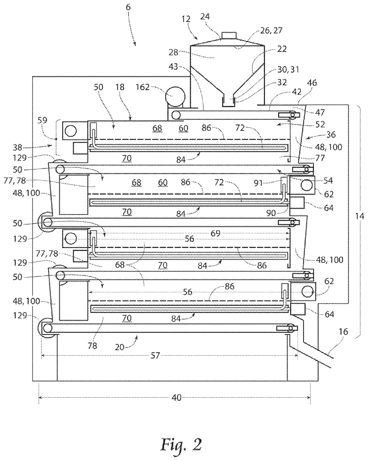
[0075]As illustrated in FIG. 8A, the radiant conveyor drying system 124 further comprises the following. The PLC 123 retrieves the measurement data from each of the at least one moisture sensor 126, the at least one second temperature sensor 127, and where applicable the at least one first temperature sensor 128. The PLC 125 computes the amount heat required to be produced by each burning unit 64 within the radiant conveyor drying system 6 in order to attain an optimum moisture reading from, the moisture sensor 126 at or in close proximity to the exit assembly 16 for the product 34. The process of measurement, calculation, and adjustment of heat produced by each burning unit 64 continues at a predetermined rate. It is observed the blower fans, conveyor motors 129 and first conveyor motor 162 are preferably maintained at a constant speed.

second embodiment

[0076]As illustrated in FIG. 8B, the radiant conveyor drying system 124′ further comprises the following. The PLC 125 retrieves the measurement data from each of the at least one moisture sensor 126, the at least one second temperature sensor 127, and where applicable the at least one first temperature sensor 128. The PLC 125 computes the amount heat required to be produced by each burning unit 64 within the radiant conveyor drying system 6 and an independent preferred speed of each conveyor motor 129 and the first conveyor motor 162 in order to attain an optimum moisture reading from the moisture sensor 126 at or in close proximity to the exit assembly 16 for the product 34. The process of measurement, calculation, and adjustment of heat produced by each burning unit 64 and speed of each conveyor motor 129 and the first conveyor motor 162 continue at independent predetermined rates. It is observed the blower fans are preferably maintained at a constant speed.

[0077]With attention to...


PUM


Abstract

A system according to the present invention provides a radiant conveyor drying system and method of operation. The radiant conveyor drying system generally comprises an input assembly, a drying assembly and an exit assembly mechanically fixed to one another. The drying assembly comprising at least one drying unit in communication with one another to provide for passage of product between the respective drying units and the input assembly and the exit assembly. The drying unit comprising a conveyor belt and a drying unit heating assembly. The drying unit heating assembly comprising a plenum and a heating chamber. The drying unit further comprising a burning unit in communication with the heating chamber to provide for radiant heat to contact the product traveling on the conveyor through the drying unit. The drying unit further comprising a blower far in communication with the plenum to provide for convective air advancing from the plenum, over and through the radiant heat, to the product. Wherein the radiant heat is disbursed throughout the product. A first embodiment of the invention controlling hear generated by the burning unit of each respective drying unit. A second embodiment of the invention controlling heat generated by the burning unit and rate of the conveyor of each respective drying unit. A method of operation of the radiant conveyor drying system is described.

Description

RELATED APPLICATIONS[0001]This application claims the benefit of co-pending provisional application Ser. No. 62 / 926,002 filed on Oct. 25, 2019.BACKGROUND OF THE INVENTION[0002]The present invention is directed generally to drying systems, and more specifically to drying systems for removing moisture from plant products, cultivated and uncultivated. More specifically, the present invention is to a radiant conveyor drying system and method of operation of the radiant conveyor drying system.[0003]The farming industry remains attentive to how much moisture is in a respective bushel or bundle of product. Additionally, providers of soil and uncultivated product parts, such as mulch, are continuously concerned with the amount of moisture within the product. Too little moisture results in a vulnerable plants prior to harvesting, and damage to product during storage due to brittleness. Too much moisture may resulting in molding of product during storage. In practice, harvesters of product se...

Claims


Application Information

Patent Timeline
IPC IPC(8): F26B23/02F26B3/06F26B3/28F26B17/08F26B25/16
CPCF26B23/02F26B3/06F26B25/16F26B17/08F26B3/283F26B21/08F26B2200/02F26B3/305F26B3/04F26B17/04F26B21/002F26B2200/06F26B2200/10F26B2200/24F26B17/001F26B17/02F26B17/026
Inventor WOOD, WILLIAM J.
Owner WOOD WILLIAM J
Learn More