Logic device using spin torque

a logic device and spin torque technology, applied in logic circuits, digital storage, instruments, etc., can solve the problems of high power consumption and heat generation, difficult to expect further density improvement,

Active Publication Date: 2021-04-29
KOREA INST OF SCI & TECH
View PDF0 Cites 0 Cited by
  • Summary
  • Abstract
  • Description
  • Claims
  • Application Information

AI Technical Summary

Benefits of technology

[0024]According to the embodiment of the present invention, it is possible to fu...

Problems solved by technology

However, recently, as silicon-based electronic device technology (complementary metal-oxide semiconductor, CMOS) is approaching physical li...

Method used


Image

  • Logic device using spin torque
  • Logic device using spin torque
  • Logic device using spin torque

Examples


Embodiment Construction

[0036]Hereinafter, embodiments of the present invention will be described in detail with reference to the drawings.

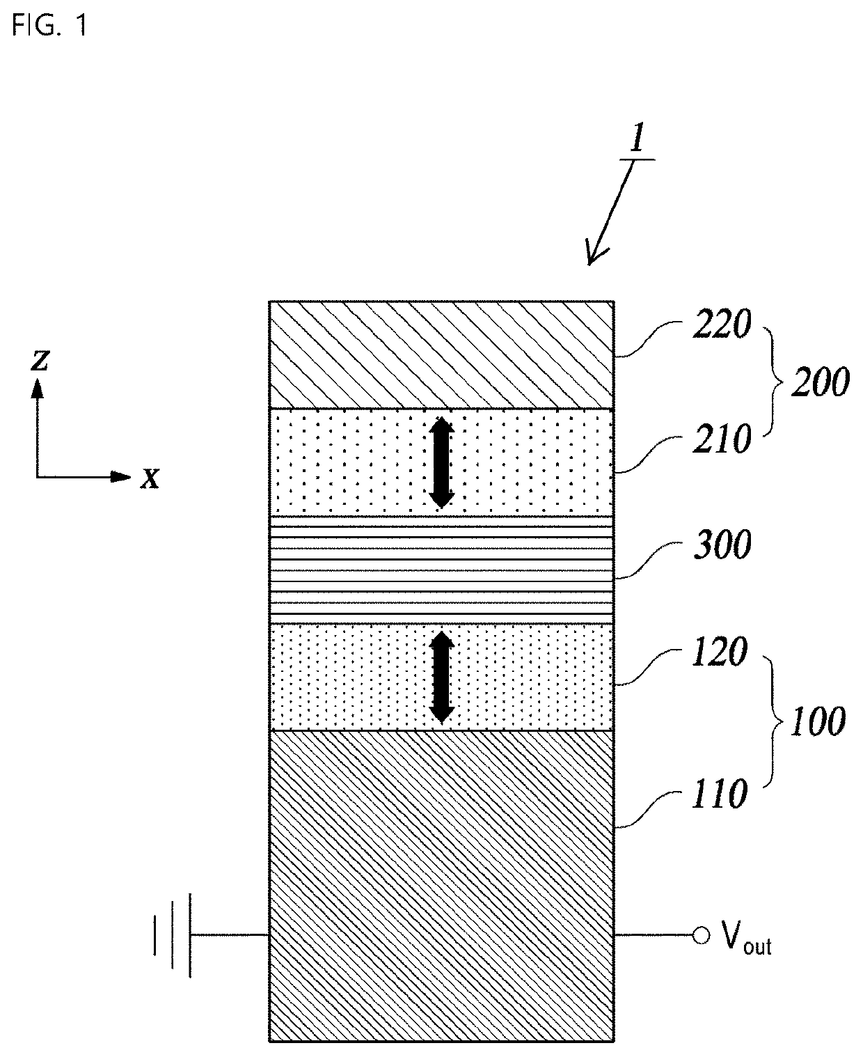
[0037]FIG. 1 is a cross-sectional view illustrating a logic function device according to an embodiment of the invention.

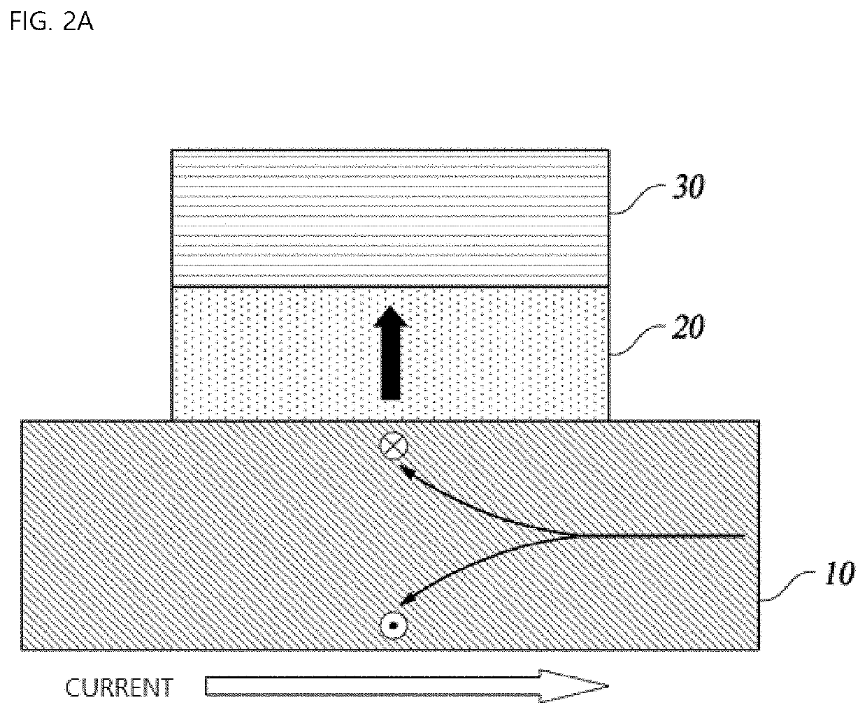
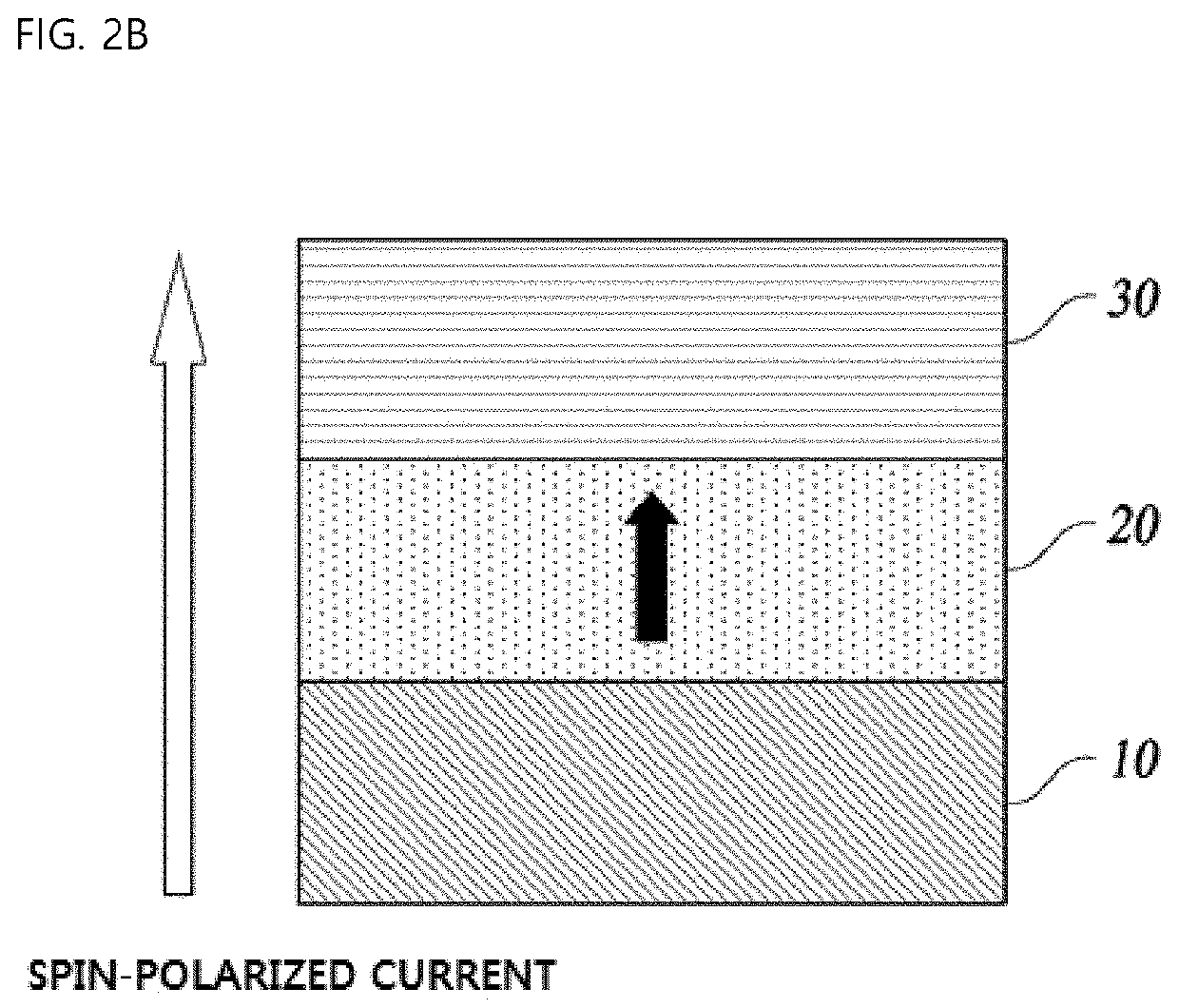
[0038]Referring to FIG. 1, the logic function device 1 includes one or more function reconfiguring units 100 having magnetization in one direction set by spin torque caused due to function reconfiguring current, and an output terminal formed at an end thereof; and at least one input unit 200 formed on the function reconfiguring unit and having magnetization in the one direction set by spin torque caused due to an input current, in which an output voltage Vout of the output terminal is determined on the basis of whether the magnetization direction of the function reconfiguring unit and the magnetization direction of the input unit are parallel or anti-parallel. An insulating tunnel junction 300 may be formed between the function reconfiguring unit 100 a...


PUM


Abstract

A logic function device according to an embodiment of the present invention includes one or more function reconfiguring units having magnetization in one direction set by spin torque caused due to an function reconfiguring current, and an output terminal formed at an end thereof; and one or more input units formed on the function reconfiguring unit and having magnetization in the one direction set by spin torque caused due to an input current, wherein an output voltage of the output terminal is determined on the basis of whether a magnetization direction of the function reconfiguring unit and a magnetization direction of the input unit are parallel or anti-parallel.

Description

CROSS REFERENCE TO RELATED APPLICATION[0001]The present application claims priority to Korean Patent Application No. 10-2019-0132010, filed Oct. 23, 2019, the entire contents of which is incorporated herein for all purposes by this reference.BACKGROUND OF THE INVENTIONField of the Invention[0002]The present invention relates to a logic function device using spin torque and, more particularly, to a logic device that is capable of reconfiguring the logic function through electrical signals in the same structure.Description of the Related Art[0003]A logic device, which performs logic operations in integrated circuits, is one of high added value products along with a memory device. However, recently, as silicon-based electronic device technology (complementary metal-oxide semiconductor, CMOS) is approaching physical limitations, it is difficult to expect further density improvement, and problems such as high power consumption and heat generation are also caused. Accordingly, it is requi...

Claims


Application Information

Patent Timeline
IPC IPC(8): H03K19/16G11C11/16H03K19/20
CPCH03K19/16H03K19/20G11C11/161G11C11/1675H10N50/10
Inventor KIM, KYOUNG WHANHAN, DONG SOOMIN, BYOUNG CHULHONG, SEOK MINKOO, HYUN CHEOLKIM, HYUNG JUNPARK, TAE EONLEE, OUK JAE
Owner KOREA INST OF SCI & TECH
Why Eureka
Try Eureka