Residual layer removal method, residual layer removal device, and display module

Inactive Publication Date: 2021-05-06
SHARP KK
View PDF0 Cites 2 Cited by
  • Summary
  • Abstract
  • Description
  • Claims
  • Application Information

AI Technical Summary

Benefits of technology

[0019]As described above, according to the technology disclosed in the present description, the residual layer of

Problems solved by technology

This is because it is likely that a connection defect will occur when the display module is produced using the substrate with the adhesive resin remaining, and it is preferable to completely remove the residual layer of the adhesive resin from the substrate at the time of regenerating the substrate.
Howev

Method used


Image

  • Residual layer removal method, residual layer removal device, and display module
  • Residual layer removal method, residual layer removal device, and display module
  • Residual layer removal method, residual layer removal device, and display module

Examples


Example

[0034]A first embodiment will be described with reference to FIGS. 1 to 10A and 10B.

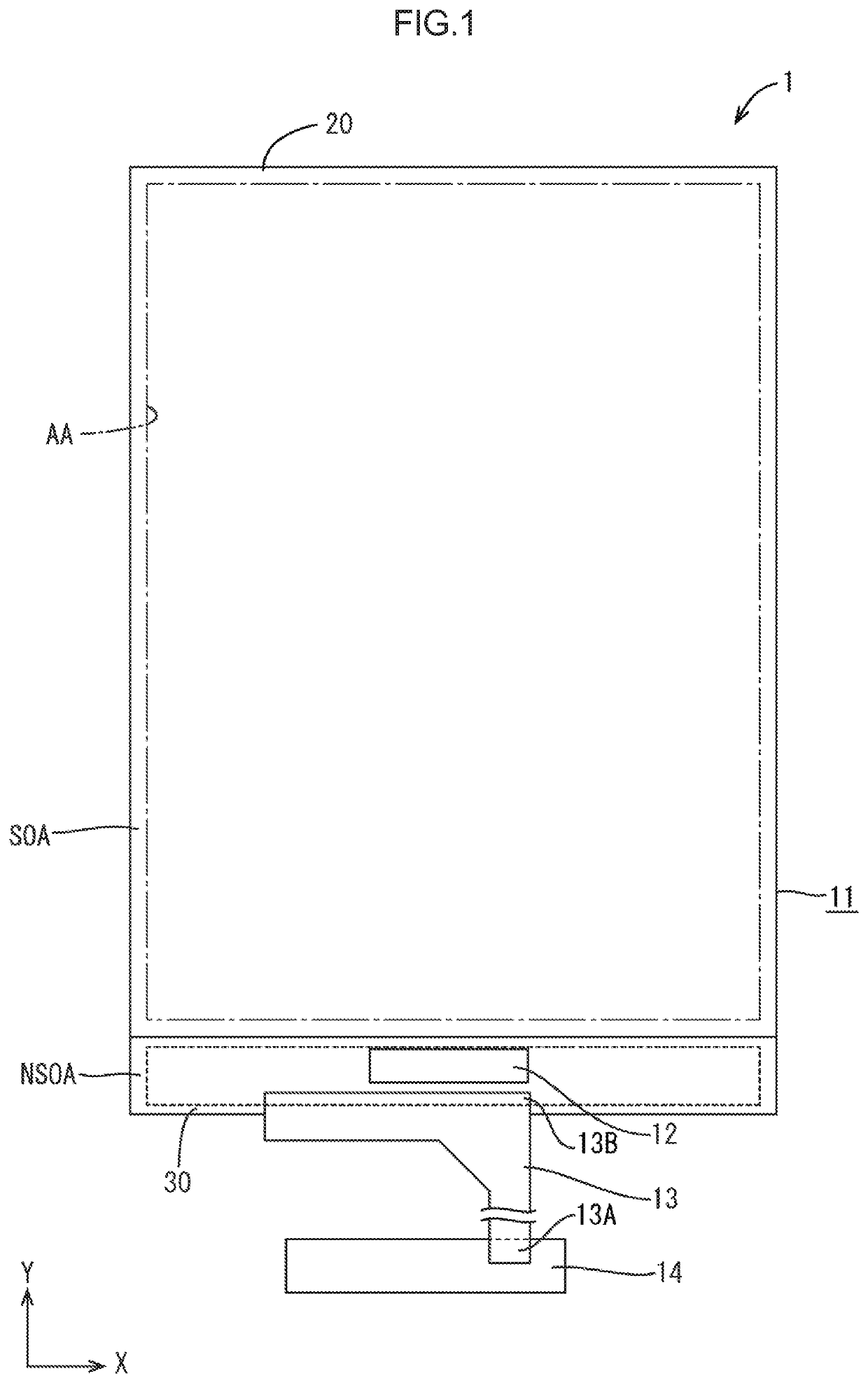
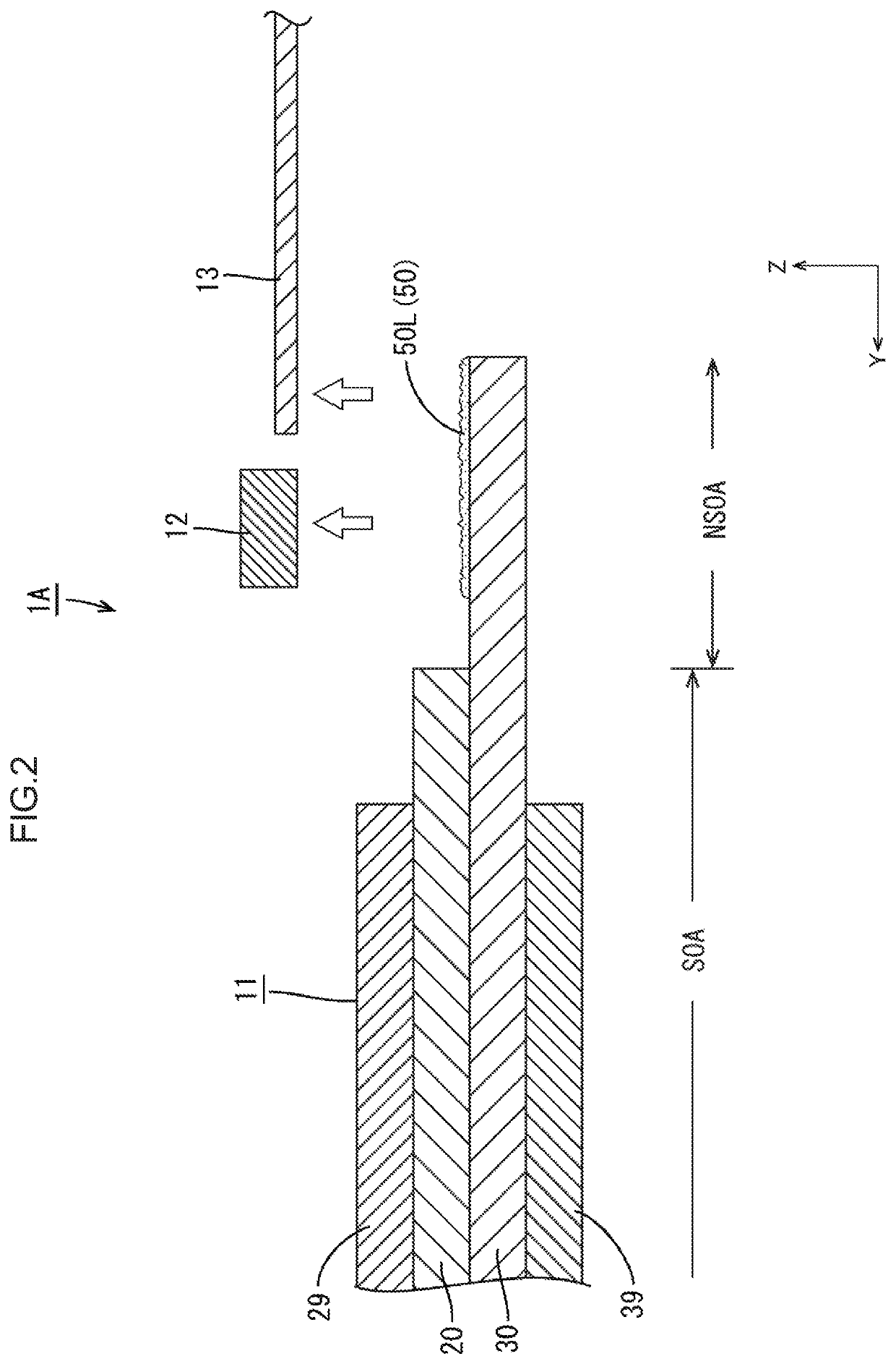
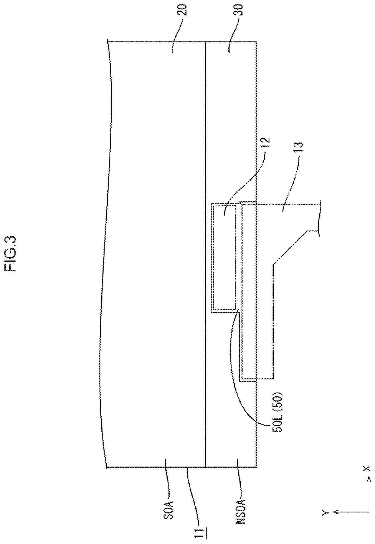
[0035]In the present embodiment, removal of an anisotropic conductive adhesive (ACF) residual layer from an array substrate constituting a liquid crystal panel (an example of a display panel) of a liquid crystal module (an example of a display module) is exemplified. Note that an X axis, a Y axis, and a Z axis are shown in some of the drawings, and each axis direction is drawn to be a direction shown in each drawing. In addition, an upper side in FIG. 1 is referred to as an upper side (a lower side in FIG. 1 is referred to as a lower side), a right side in FIG. 1 s referred to as a right side (a left side in FIG. 1 is referred to as a left side), a front side of a paper is referred to as a front side (a back side of the paper is referred to as a back side), and reference numerals may be given to some of members that are the same as each other and may be omitted for the other members.

[0036]As shown in...

Example

Second Embodiment

[0105]A second embodiment will be described with reference to FIG. 11. In the second. embodiment, a structure of a metal mesh is different from that of the first embodiment. Hereinafter, an overlapping description of the same configuration, action, and effect as those of the first embodiment described above will be omitted (the same applies to a third embodiment).

[0106]FIG. 11 is a view schematically showing a cross-sectional configuration of a metal mesh 260 according to the second embodiment together with a cross section of a residual layer 250L that is a target to be removed. The metal mesh 260 according to the second embodiment is a multilayer planar body in which a structure in which metal wires 260B are knitted is formed in multiple layers. The metal wires 260B forming the metal mesh 260 used in the present embodiment have a diameter d smaller than an average layer thickness 1 of the residual layer 250L (d≤1).

[0107]According to the configuration of the second ...

Example

Third Embodiment

[0108]A third embodiment will be described with reference to FIG. 12. Also in the third embodiment, a structure of a metal mesh is different from that of the first embodiment.

[0109]FIG. 12 is a view schematically showing a cross-sectional configuration of a metal mesh 360 according to a third embodiment. In the metal mesh 360 according to the present embodiment, at least parts of surfaces of open holes 360A, that is, outer peripheral surfaces of metal wires 360B are covered with the same resin as that of a residual layer 350L formed of an ACF 350, that is, the ACF 350. Note that a resin having surface energy close to an adhesive resin, such as a resin containing the same kind of functional group as that of the adhesive resin, can be used as a covering resin having an excellent affinity with the adhesive resin. In addition, as the metal mesh 360, a metal mesh 360 in which the metal wires 60B are coated with the ACF 350 can be used. Alternatively, a resin film may be i...


PUM


Abstract

A residual layer removal method of removing a residual layer of an adhesive resin attached to a substrate used in a display module, the residual layer removal method includes: an arranging step of arranging a metal porous material on a surface of the residual layer; a heating step of heating and softening the residual layer; a pressing step of pressing the metal porous material arranged on the surface of the residual layer by the arranging step to the residual layer softened. by the heating step to press-fit at least parts of the residual layer into open holes of the metal porous material; and a peeling step of peeling off the metal porous material in which the residual layer is press-fitted into the open holes from the substrate.

Description

TECHNICAL FIELD[0001]The present technology relates to a residual layer removal method, a residual layer removal device, and a display module.BACKGROUND ART[0002]As a display module, a display module including a display panel configured to display an image, a driver (integrated circuit (IC) chip) driving the display panel, a control circuit board supplying various input signals from the outside to the drive, and a flexible printed circuit (FPC) board (flexible circuit board) electrically connecting the external control circuit board and the display panel to each other has been known. Electrical components such as the driver, the FPC board or the like are usually bonded and fixed and are electrically connected onto a glass substrate constituting the display panel through an anisotropic conductive adhesive (ACF) or the like. In the present description, any component provided with a contact portion that performs electrical connection by contact is referred to as an electrical component...

Claims


Application Information

Patent Timeline
IPC IPC(8): B32B37/12G02F1/1339
CPCB32B37/1207B32B2457/202G02F2202/28G02F1/1339G09F9/00G02F1/13452
Inventor HIRANO, TAKAAKI
Owner SHARP KK
Why Eureka
Try Eureka