Check patentability & draft patents in minutes with Patsnap Eureka AI!

Cooling system for power storage

Pending Publication Date: 2021-05-13
TOYOTA JIDOSHA KK
View PDF2 Cites 0 Cited by
  • Summary
  • Abstract
  • Description
  • Claims
  • Application Information

AI Technical Summary

Benefits of technology

The patent text describes a control system for a power storage device. The system uses condition-based data to provide information to the user and control the cooling system of the device. This helps prevent over-cooling or failure of the device, while also improving the user's experience by reducing the discomfort caused by the cooling system. The technical effects of this system include improved reliability and user experience.

Problems solved by technology

When a temperature of the power storage becomes high, loss may increase or deterioration may be accelerated due to increase in internal resistance.
When the cooling system is activated, noise is generated.
Therefore, improvement in quiet performance by delaying cooling timing or extension of life by advancing cooling timing regardless of product characteristics on which a user places importance may not lead to execution of control of the cooling system in conformity with product characteristics on which the user places importance.
Frequent representation of inquiry information as to whether or not cooling can be carried out during such a period may sometimes make the user feel bothered and product characteristics as preferred by the user may not be achieved.
Providing the user with inquiry information each time the execution condition is satisfied may make the user feel bothered, and product characteristics as preferred by the user may not be achieved.
If no change from the previous operation can be made in such a case, product characteristics as preferred by the user may not be achieved.
Thus, when the power storage is in the abnormal condition, cooling of the power storage is forcibly carried out.
Thus, when the temperature of the power storage is high, cooling of the power storage is forcibly carried out.
Thus, the user can recognize an advantage and a disadvantage in carrying out cooling.
Thus, the user can recognize an advantage and a disadvantage in not carrying out cooling.

Method used


Image

  • Cooling system for power storage
  • Cooling system for power storage
  • Cooling system for power storage

Examples


Embodiment Construction

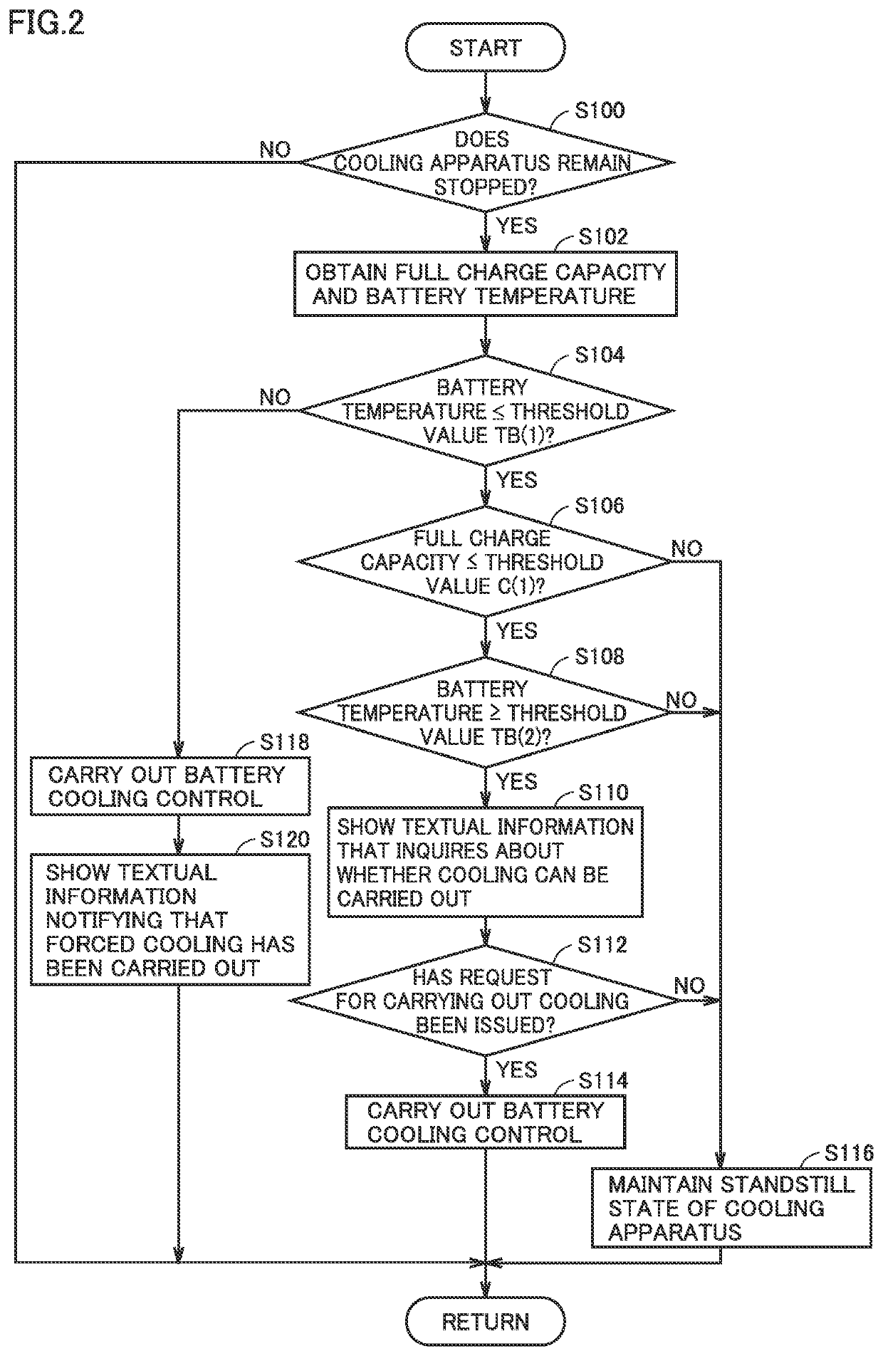
[0048]An embodiment of the present disclosure will be described below in detail with reference to the drawings. The same or corresponding elements in the drawings have the same reference characters allotted and description thereof will not be repeated.

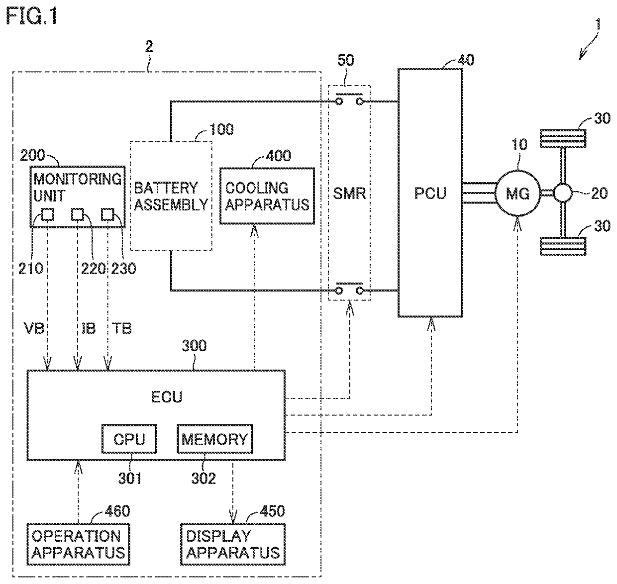
[0049]An example in which a cooling system for a power storage according to an embodiment of the present disclosure is mounted on a vehicle will be described below by way of example. FIG. 1 is a diagram showing an exemplary configuration of a vehicle 1 incorporating a cooling system 2.

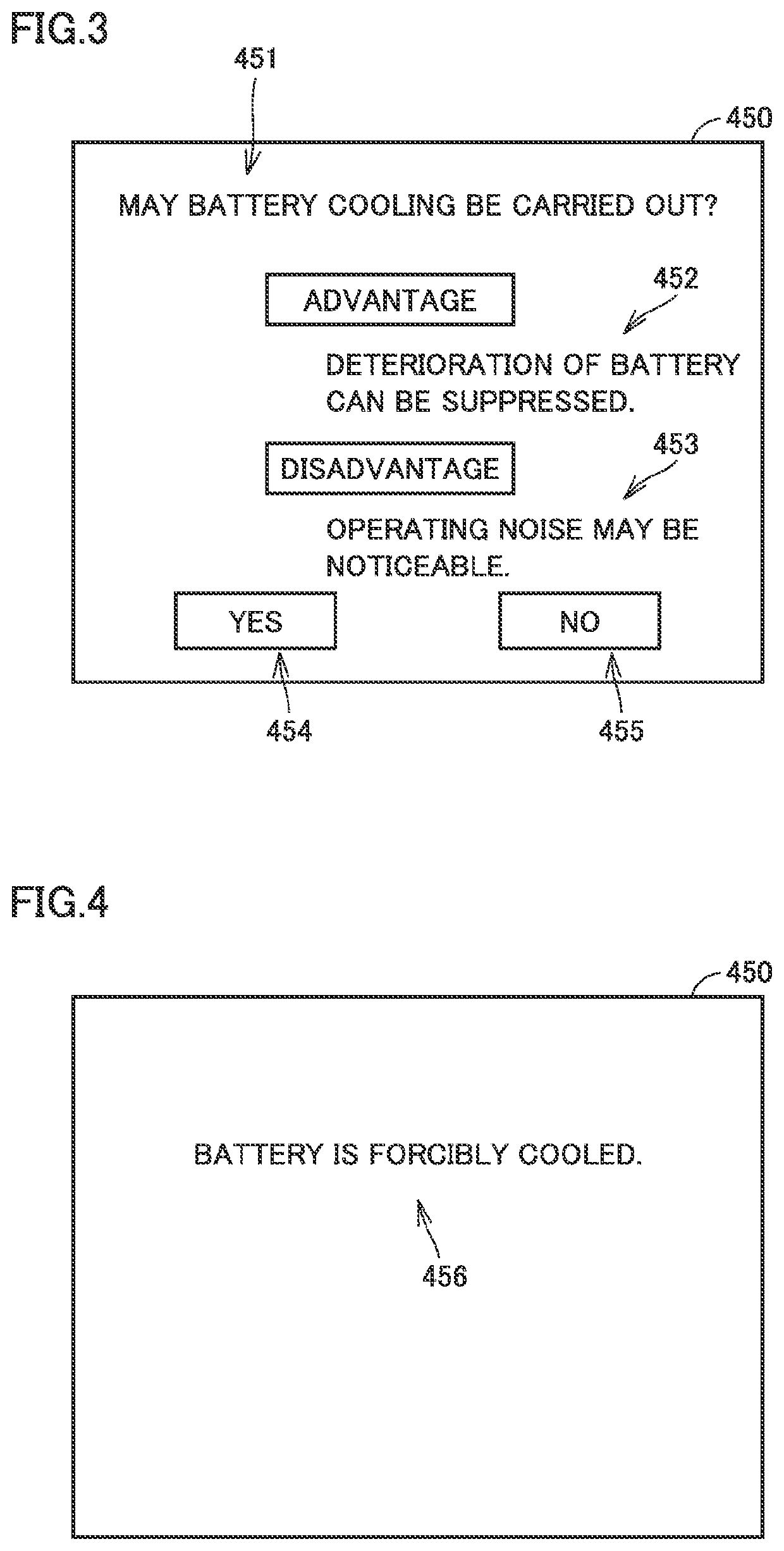
[0050]In the present embodiment, for example, an electric vehicle is adopted as vehicle 1. Vehicle 1 includes cooling system 2, a motor generator (MG) 10, a power transmission gear 20, a drive wheel 30, a power control unit (PCU) 40, and a system main relay (SMR) 50. In the present embodiment, cooling system 2 includes a battery assembly 100, a monitoring unit 200, an electronic control unit (ECU) 300, a cooling apparatus 400, a display apparatus 450, and...


PUM


Abstract

An ECU performs processing including obtaining a full charge capacity when a cooling apparatus remains stopped, showing textual information that inquires about whether or not cooling can be carried out when a battery temperature is equal to or lower than a threshold value TB(1), when the full charge capacity is equal to or lower than a threshold value C(1), and when the battery temperature is equal to or higher than a threshold value TB(2), carrying out battery cooling control when a request for carrying out cooling has been issued, and maintaining a standstill state of the cooling apparatus when no request for carrying out cooling has been issued.

Description

[0001]This nonprovisional application is based on Japanese Patent Application No. 2019-202460 filed with the Japan Patent Office on Nov. 7, 2019, the entire contents of which are hereby incorporated by reference.BACKGROUNDField[0002]The present disclosure relates to a cooling system for a power storage.Description of the Background Art[0003]An electrically powered vehicle such as an electric vehicle or a hybrid vehicle that travels with electric power incorporates a power storage such as a secondary battery that stores electric energy. The power storage generates heat by being charged or discharging. When a temperature of the power storage becomes high, loss may increase or deterioration may be accelerated due to increase in internal resistance. Therefore, the electrically powered vehicle incorporating the power storage may incorporate a cooling system for the power storage. When the cooling system is activated, noise is generated. Therefore, the cooling system is desirably activate...

Claims


Application Information

Patent Timeline
IPC IPC(8): B60L58/26H01M10/625B60L58/12
CPCB60L58/26B60L58/12H01M10/625H01M10/613H01M10/633H01M10/486H01M10/663H01M2220/20H01M10/6556Y02T10/70Y02E60/10B60L2240/545
Inventor YOSHIDA, HIROSHITANAKA, NOBUYUKIKUBO, KAZUKI
Owner TOYOTA JIDOSHA KK
Features
  • R&D
  • Intellectual Property
  • Life Sciences
  • Materials
  • Tech Scout
  • Unparalleled Data Quality
  • Higher Quality Content
  • 60% Fewer Hallucinations
Learn More