Welding shield

a shield and welding technology, applied in the field of welding shields, can solve the problems of deficient shields when it comes to accommodating various pipe diameters and flat materials, deficient shields when it comes to shielding various materials, and insufficient gas distribution of current welding shields. achieve the effect of improving gas distribution

Inactive Publication Date: 2021-05-20
PETTERSSON CARL +1
View PDF4 Cites 0 Cited by
  • Summary
  • Abstract
  • Description
  • Claims
  • Application Information

AI Technical Summary

Benefits of technology

[0005]It is the object of the present invention to provide a welding shield that is configured to provide improved gas distribution during the welding process of metals such as but not limited to exotic metals wherein the present invention includes a central member.
[0006]Another object of the present invention is to provide a welding shield operable to assist in the improved welding of exotic metals wherein the central member includes an interior volume that is substantially hollow and has an opening on the bottom thereof.
[0007]A further object of the present invention is to provide a welding shield that is configured to provide improved gas distribution during the welding process of metals such as but not limited to exotic metals that further includes a plurality of wing members wherein the wing members releasably secure to opposing sides of the central member.

Problems solved by technology

One problem with welding exotic metals is ensuring the flow and distribution of gas during the welding process.
A good weld bead is more difficult to obtain for metals such as but not limited to metals having high nickel alloys.
While there are commercially available tools such as but not limited to wielding shields, these shields are deficient when it comes to accommodating various pipe diameters and flat materials.
Furthermore, in the arena of pipe welding, current welding shields are not configured to further provide assistance in cutting of the pipe with tools such as but not limited to plasma cutters.

Method used


Image

  • Welding shield
  • Welding shield
  • Welding shield

Examples


Embodiment Construction

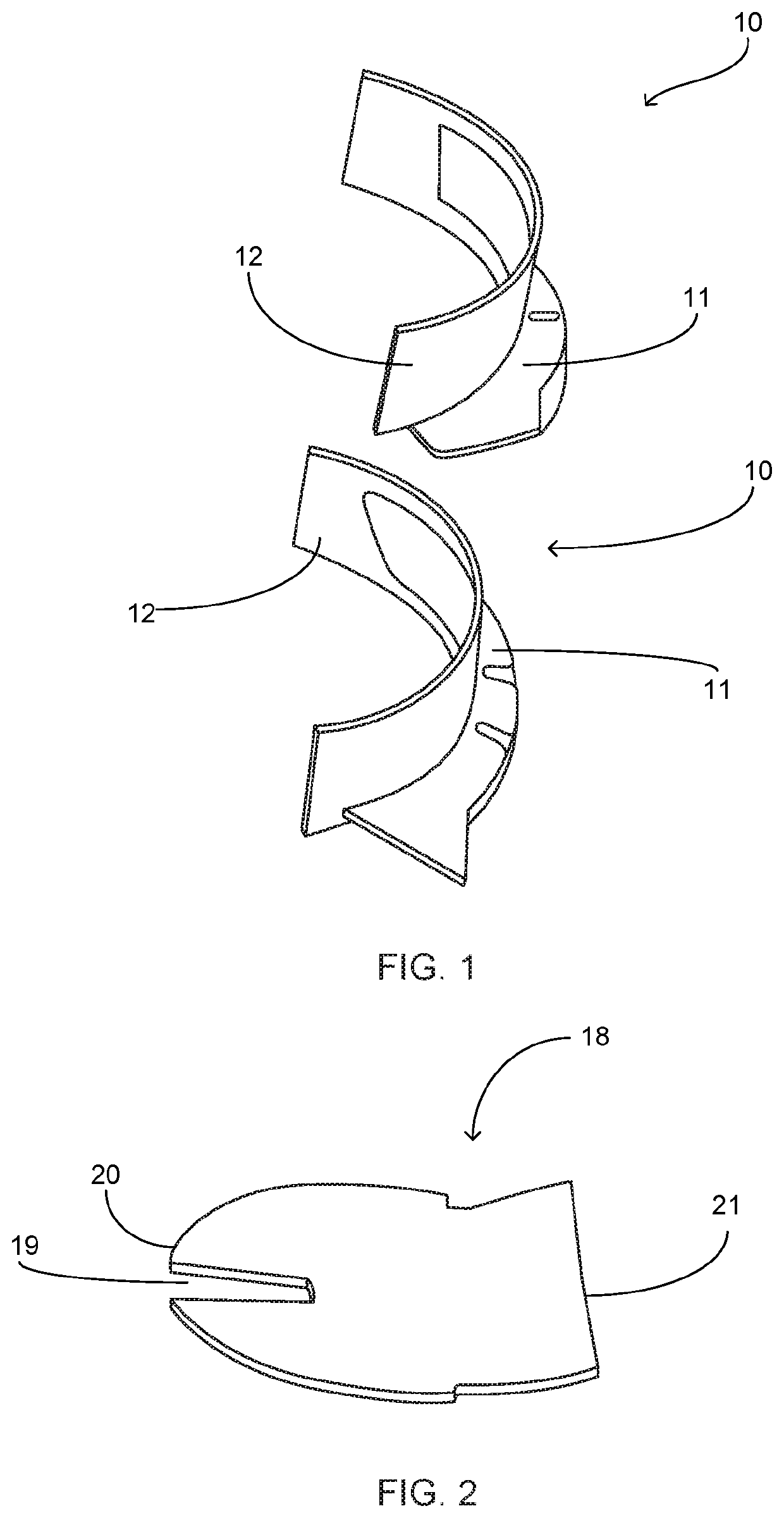
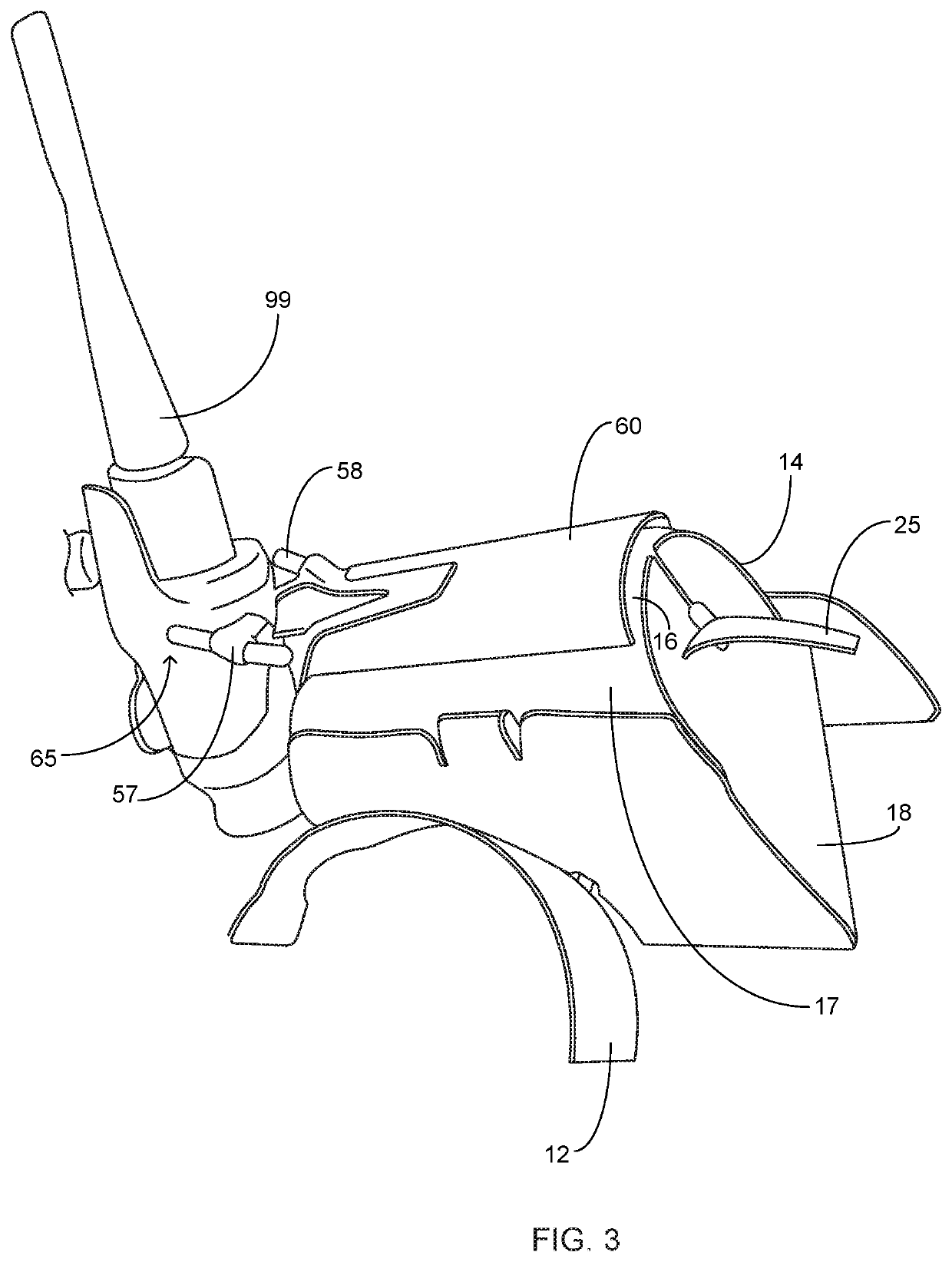
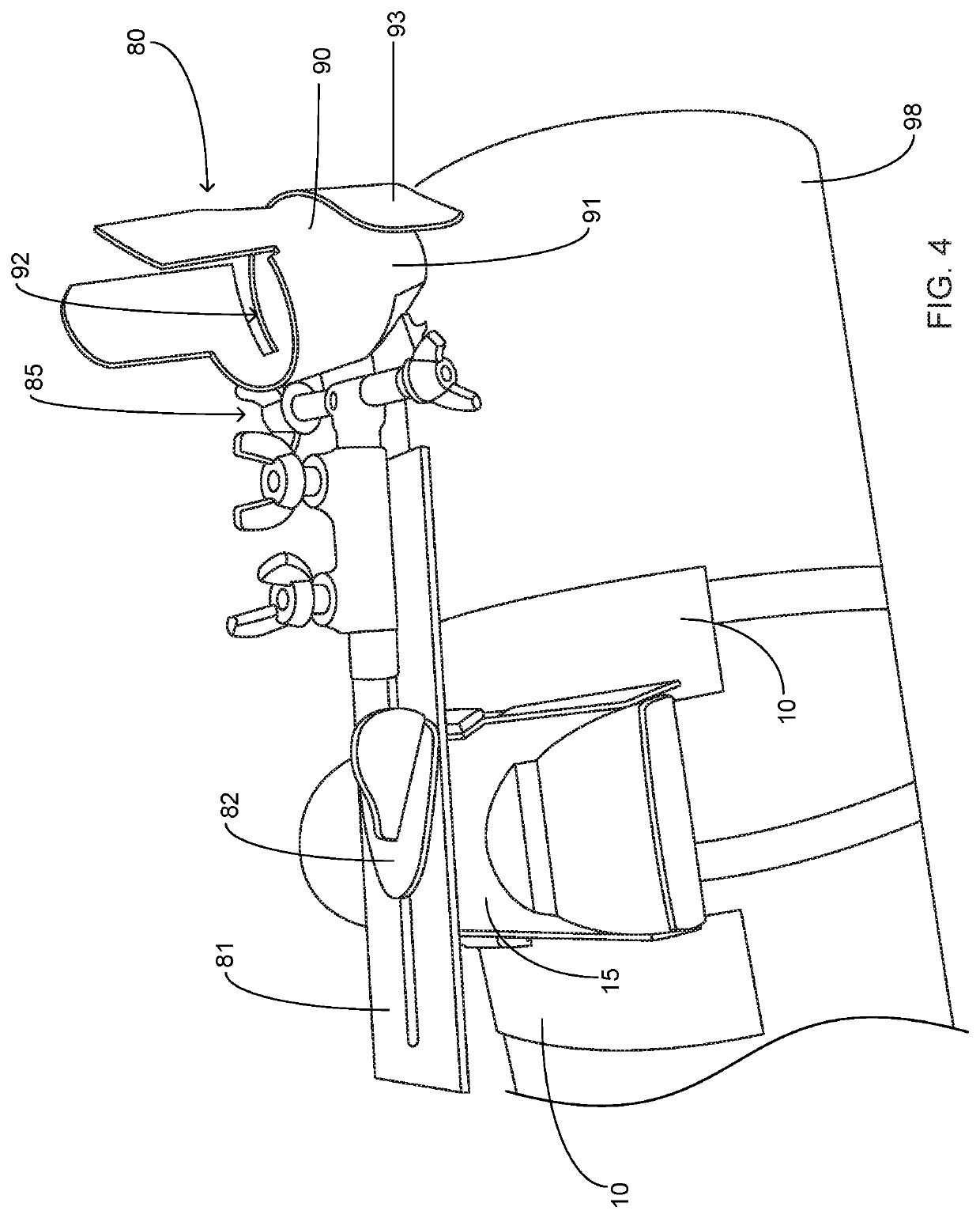
[0023]Referring now to the drawings submitted herewith, wherein various elements depicted therein are not necessarily drawn to scale and wherein through the views and figures like elements are referenced with identical reference numerals, there is illustrated a welding shield 100 constructed according to the principles of the present invention.

[0024]An embodiment of the present invention is discussed herein with reference to the figures submitted herewith. Those skilled in the art will understand that the detailed description herein with respect to these figures is for explanatory purposes and that it is contemplated within the scope of the present invention that alternative embodiments are plausible. By way of example but not by way of limitation, those having skill in the art in light of the present teachings of the present invention will recognize a plurality of alternate and suitable approaches dependent upon the needs of the particular application to implement the functionality...


PUM

PropertyMeasurementUnit
diametersaaaaaaaaaa
interior volumeaaaaaaaaaa
volumeaaaaaaaaaa

Abstract

A welding shield that is configured to provide improved gas distribution adjacent a weld seam during the welding process so as to improve the weld quality. The welding shield includes a central member wherein the central member includes contiguously formed sidewalls and a top wall operable to create an interior volume. Mounted within the interior volume is a gas distribution module that is operably coupled to a gas source. A clip member is mounted to the central member and is configured to provide retention of the gas distribution module. A torch retention member is movably mounted to the top wall of the central member. The torch retention member is configured to receive and secure a welding torch and further provide rotational and pivotal movement thereof. A plasma cutter holding member is further included and is operable to releasably retain a plasma cutter.

Description

FIELD OF THE INVENTION[0001]The present invention relates generally to welding implements, more specifically but not by way of limitation, a welding shield that is configured to provide improved gas coverage during the welding process so as to increase the quality of welds on metals such as but not limited to exotic metals.BACKGROUND[0002]Welding is a common technique in many industries and involves the joining of like metals utilizing welding techniques such as but not limited to TIG and / or MIG welding. While welding ferrous metals is fairly routine and can be executed by most welders, the welding of exotic metals such as but not limited to titanium requires a bit more skill and control of other parameters. In order to execute a good weld on exotic metals one of the key parameters to control is gas distribution. As is known in the art, argon gas is commonly utilized in welding. Argon gas or gas blends including argon are utilized in welding to create an inert gas shield during the ...

Claims


Application Information

Patent Timeline
Patent Type & Authority Applications(United States)
IPC IPC(8): B23K9/29B23K9/16B23K9/167B23K10/00
CPCB23K9/296B23K10/00B23K9/167B23K9/164B23K9/325B23K9/321
Inventor PETTERSSON, CARLPETTERSSON, STIG
Owner PETTERSSON CARL
Why Eureka
Try Eureka