Decommissioning method of biodegradable concrete of pwr type nuclear power plant

a biodegradable concrete and nuclear power plant technology, applied in the field of nuclear power plant decommissioning method, can solve the problems of increased decommissioning process time, movement of radioactive dust, and increased risk of radioactive exposure of workers, so as to reduce the generation of radioactive dust, reduce the risk of workers being exposed, and reduce the effect of decommissioning process tim

Active Publication Date: 2021-05-27
KOREA HYDRO & NUCLEAR POWER CO LTD
View PDF0 Cites 1 Cited by
  • Summary
  • Abstract
  • Description
  • Claims
  • Application Information

AI Technical Summary

Benefits of technology

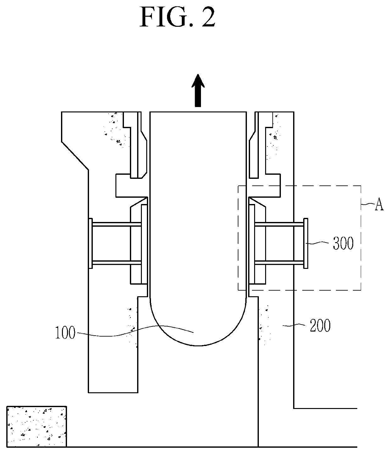
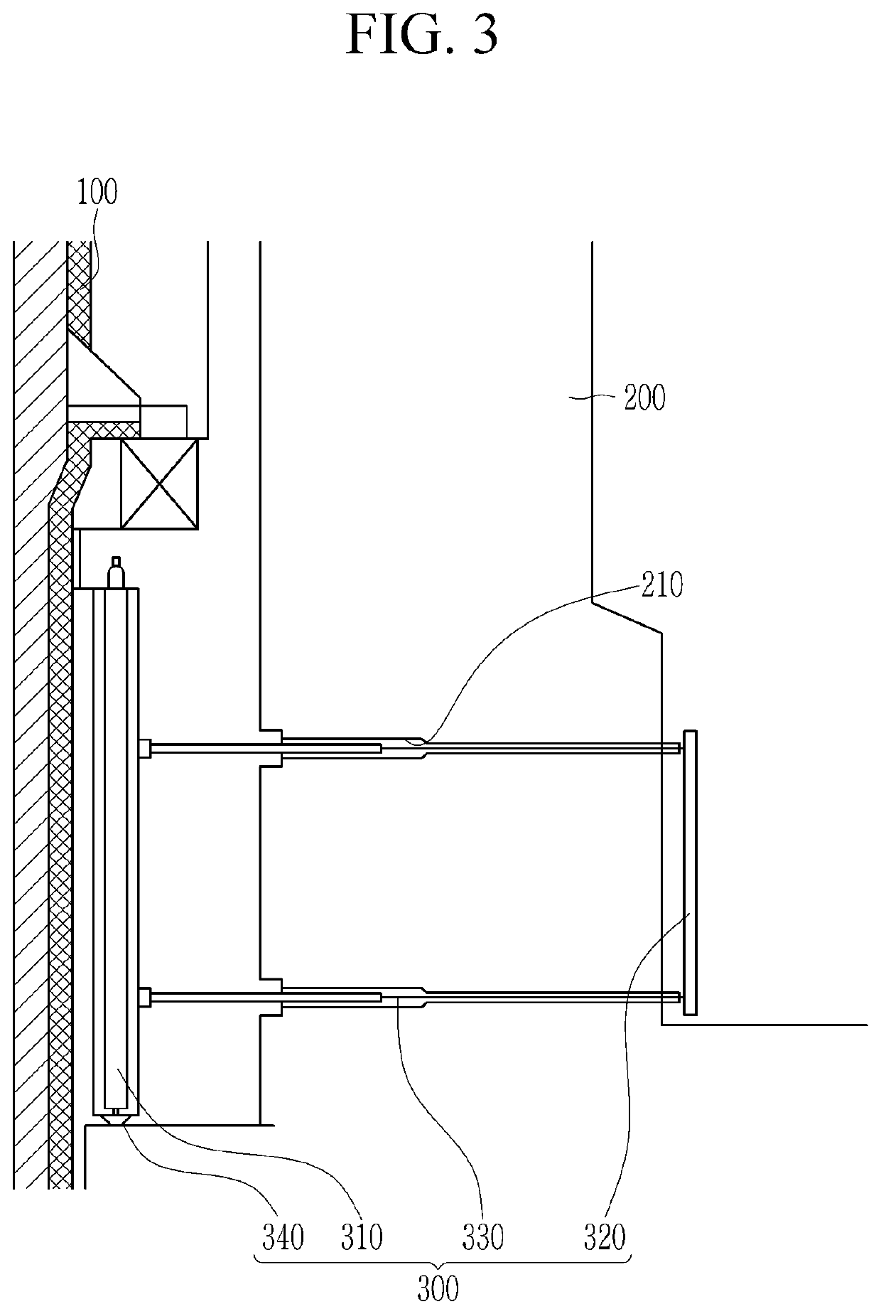
[0014]According to an exemplary embodiment, as the cutting and decommissioning processes are performed without additional coring work on the biodegradable concrete by inserting the decommissioning device into the penetrated part of the neutron detector positioning device installed inside the biodegradable concrete, the decommissioning process time may be shortened.
[0015]In addition, since there is no separate coring work, generation of the radioactive dust may be minimized, thus minimizing worker exposure.

Problems solved by technology

The biodegradable concrete forms a large cylindrical reinforced concrete structure by stacking a plurality of layers, and since the biodegradable concrete is most severely contaminated with a radioactive material, when decommissioning a pressurized light water reactor (PWR) type of nuclear power plant that has expired and is permanently stopped, workers are likely to be exposed.
When a hole is formed in the biodegradable concrete to insert a decommissioning device into the biodegradable concrete, radioactive dust is generated, so there is a risk of radioactive exposure and movement of the radioactive dust.
In addition, since the process of forming the holes in the biodegradable concrete is added, a decommissioning process time increases.

Method used


Image

  • Decommissioning method of biodegradable concrete of pwr type nuclear power plant
  • Decommissioning method of biodegradable concrete of pwr type nuclear power plant
  • Decommissioning method of biodegradable concrete of pwr type nuclear power plant

Examples


Embodiment Construction

[0023]The present invention will be described more fully hereinafter with reference to the accompanying drawings, in which exemplary embodiments of the invention are shown. As those skilled in the art would realize, the described embodiments may be modified in various different ways, all without departing from the spirit or scope of the present invention.

[0024]In order to clearly explain the present invention, portions that are not directly related to the present invention are omitted, and the same reference numerals are attached to the same or similar constituent elements through the entire specification.

[0025]In addition, the size and thickness of each configuration shown in the drawings are arbitrarily shown for better understanding and ease of description, but the present invention is not limited thereto.

[0026]In the drawings, the thickness of layers, films, panels, regions, etc., are exaggerated for clarity. In the drawings, for better understanding and ease of description, the...


PUM

PropertyMeasurementUnit
pressureaaaaaaaaaa
diameteraaaaaaaaaa
temperatureaaaaaaaaaa

Abstract

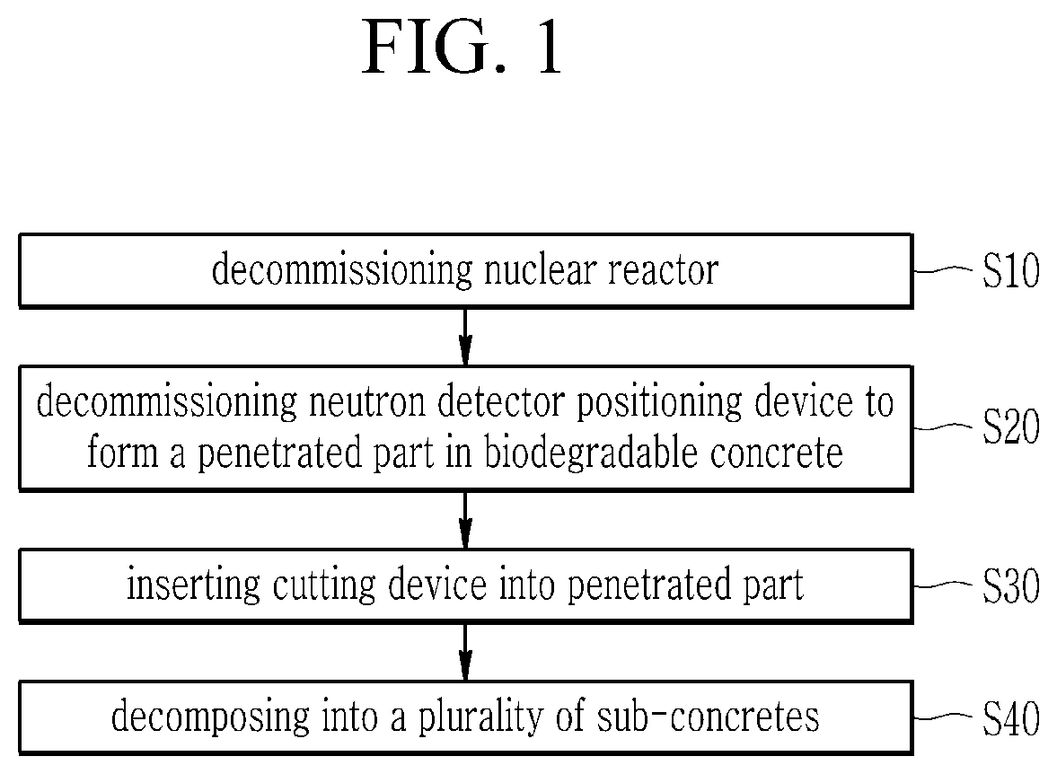
A decommissioning method of biodegradable concrete of a nuclear power plant according to an exemplary embodiment includes: decommissioning a neutron detector positioning device installed to biodegradable concrete surrounding a nuclear reactor to form a plurality of penetrated parts in the biodegradable concrete; inserting a part of a cutting device into the plurality of penetrated parts; and decomposing the biodegradable concrete into a plurality of sub-concrete parts by using the cutting device.

Description

TECHNICAL FIELD[0001]The present disclosure relates to a decommissioning method of biodegradable concrete of a nuclear power plant. More particularly, the present invention relates to a decommissioning method of biodegradable concrete of a PWR type of nuclear power plant.BACKGROUND ART[0002]As a fossil energy is depleted worldwide, nuclear power generation is being used as a major energy source. In such nuclear power generation, a generally-used pressurized water reactor (PWR) nuclear power plant consists of a primary system circulating in a nuclear reactor, a secondary system circulating in a steam generator, and a tertiary system circulating in a condenser. Specifically, in the primary system, a pressure is applied to a coolant contained in a reactor to maintain 150 atm and 300° C., and in the secondary system, the coolant boils water on the side of the steam generator while passing through the steam generator to generate steam to turn a turbine. In the tertiary system, the steam ...

Claims


Application Information

Patent Timeline
Patent Type & Authority Applications(United States)
IPC IPC(8): G21D1/00
CPCG21D1/003Y02E30/30Y02E30/00G21F9/28G21F9/30B28D1/088G21C1/086G21C17/116
Inventor HWANG, SEOK-JUHONG, SUNG-HOONLEE, MI-HYUNKIM, CHEON-WOO
Owner KOREA HYDRO & NUCLEAR POWER CO LTD
Why Eureka
Try Eureka