
Infrastructure equipment, wireless communications network, communication device and methods

a technology for infrastructure equipment and wireless communications, applied in the field of infrastructure equipment, can solve the problems of draining battery life, pss and sss can take a relatively long time,

Active Publication Date: 2021-06-03
SONY CORP
View PDF1 Cites 1 Cited by
  • Summary
  • Abstract
  • Description
  • Claims
  • Application Information

AI Technical Summary

Benefits of technology

This patent describes a technique for improving the synchronization of communication devices in a wireless network. The technique involves transmitting two synchronization signals: a first, conventional signal and an enhanced synchronization signal. The enhanced signal contains a set of sequences that can identify the unique identifier of a cell, as well as other indicators of system information. This allows devices to quickly detect and synchronize with the network, without having to use the conventional signal, which can take longer and drain battery life. The technique also allows for the efficient detection of other information, such as a system information change notification or wake-up signals.

Problems solved by technology

However, detecting the PSS and the SSS can take a relatively long time.
As a result, when such devices come out of a DRX cycle they may have lost synchronisation due to clock drifts and / or moved to a different cell, therefore requiring them to re-acquire synchronisation and detect the PCID of the cell in which they wish to communicate.
However using a conventional (first) synchronisation signal such as a PSS / SSS to re-synchronise with the wireless access interface can take a relatively long time therefore causing a drain of battery life.

Method used


Image

  • Infrastructure equipment, wireless communications network, communication device and methods
  • Infrastructure equipment, wireless communications network, communication device and methods
  • Infrastructure equipment, wireless communications network, communication device and methods

Examples


Embodiment Construction

[0027]Long Term Evolution (LTE) Wireless Communications System

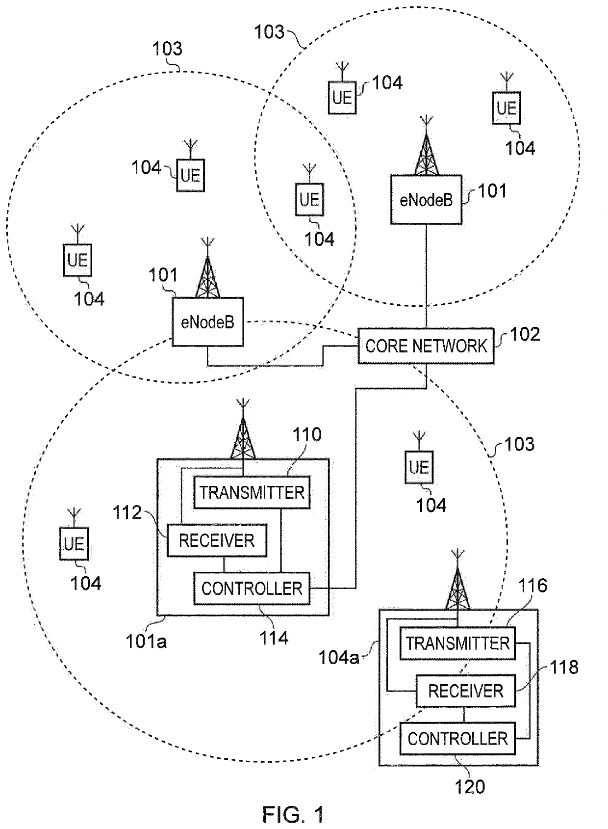
[0028]FIG. 1 provides a schematic diagram illustrating some basic functionality of a mobile telecommunications network / system operating in accordance with LTE principles and which may be adapted to implement embodiments of the disclosure as described further below. Various elements of FIG. 1 and their respective modes of operation are well-known and defined in the relevant standards administered by the 3GPP® body, and also described in many books on the subject, for example, Holma H. and Toskala A [13]. It will be appreciated that operational aspects of the telecommunications network which are not specifically described below may be implemented in accordance with any known techniques, for example according to the relevant standards.

[0029]FIG. 1 provides a schematic diagram of a mobile telecommunications system, where the system includes infrastructure equipment comprising base stations 101 which are connected to a core ne...


PUM


Abstract

A method of operating a communications device to transmit data to or to receive data from a wireless communications network comprises detecting a first synchronisation signal at the communications device received via a wireless access interface of a cell of the wireless communications network, the first synchronisation signal being transmitted with a first periodicity with respect to a time divided structure of the wireless access interface, the first synchronisation signal being configured to carry an indication of an identifier of the cell, generating a first estimate of the cell identifier carried by the first synchronisation signal, and configuring a transmitter of the communications device to transmit data to the wireless communications network and configuring a receiver of the communications device to receive data from the wireless communications network based on the first estimated cell identifier.

Description

CROSS-REFERENCE TO RELATED APPLICATIONS[0001]The present application is based on PCT filing PCT / EP2019 / 059554, filed Apr. 12, 2019, which claims priority to EP 18167615.6, filed Apr. 16, 2018, the entire contents of each are incorporated herein by reference.BACKGROUNDField of Disclosure[0002]The present disclosure relates to infrastructure equipment which form part of a radio access network of a mobile communications network, which are configured to transmit synchronisation signals to communications devices for the communications devices to synchronise with a wireless access interface provided by the radio network part of the wireless communications network in order to transmit or to receive data. The present technique also relates to communications devices configured to synchronise with a wireless communications network in order to transmit or to receive data via the wireless communications networks and method of the same.Description of Related Art[0003]The “background” description...

Claims


Application Information

Patent Timeline
Patent Type & Authority Applications(United States)
IPC IPC(8): H04W56/00H04W52/02
CPCH04W56/0015H04W52/0216Y02D30/70
Inventor WONG, SHIN HORNGBEALE, MARTIN WARWICK
Owner SONY CORP
Learn More