
Motion artifact prediction during data acquisition

a technology of magnetic resonance imaging and data acquisition, applied in image enhancement, instruments, applications, etc., can solve the problems that magnetic resonance images may be of little or even no use for medical diagnosis, and achieve the effect of effective and efficient, effective and efficien

Active Publication Date: 2021-06-17
KONINKLJIJKE PHILIPS NV
View PDF0 Cites 8 Cited by
  • Summary
  • Abstract
  • Description
  • Claims
  • Application Information

AI Technical Summary

Benefits of technology

The patent text describes a method for improving the efficiency and quality of magnetic resonance imaging (MRI) by using deep learning to detect and correct for motion artifacts. This technique allows for faster data acquisition and ensures that the resulting images are of higher quality. The method also provides a way to efficiently train the deep learning network for motion-artifact-only MRI data. Overall, this approach enhances the overall workflow and data quality in MRI.

Problems solved by technology

Due to typically long data acquisition times of magnetic resonance imaging (MRI) procedures, motion artifacts caused by patient motion are one of the most frequent causes of image degradation of magnetic resonance images in clinical applications of MRI.
Possible problems associated with motion artifacts may for example comprise that the respective magnetic resonance images may be of little or even no use for medical diagnosis due to the image degradation.

Method used


Image

  • Motion artifact prediction during data acquisition
  • Motion artifact prediction during data acquisition
  • Motion artifact prediction during data acquisition

Examples


Embodiment Construction

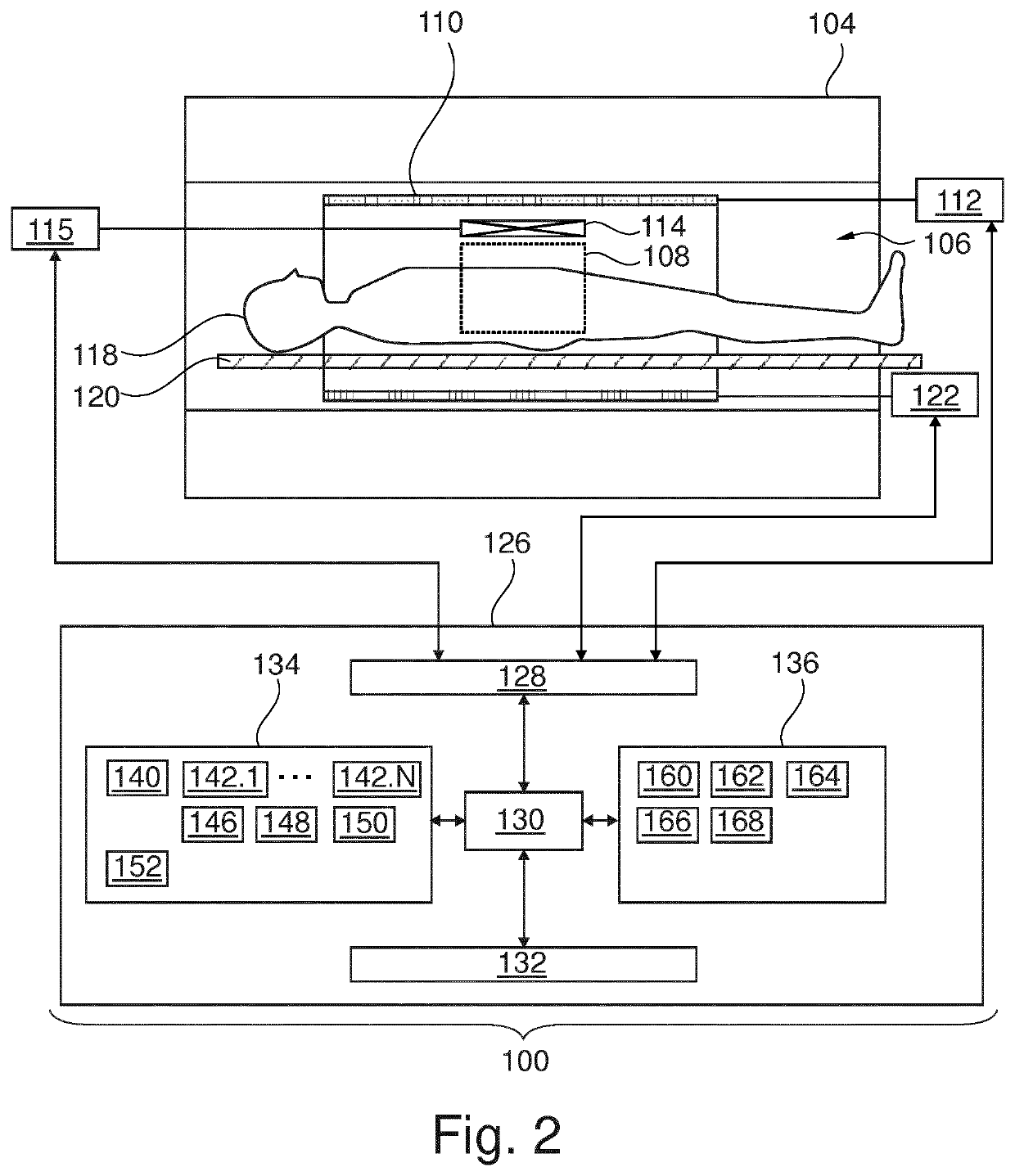
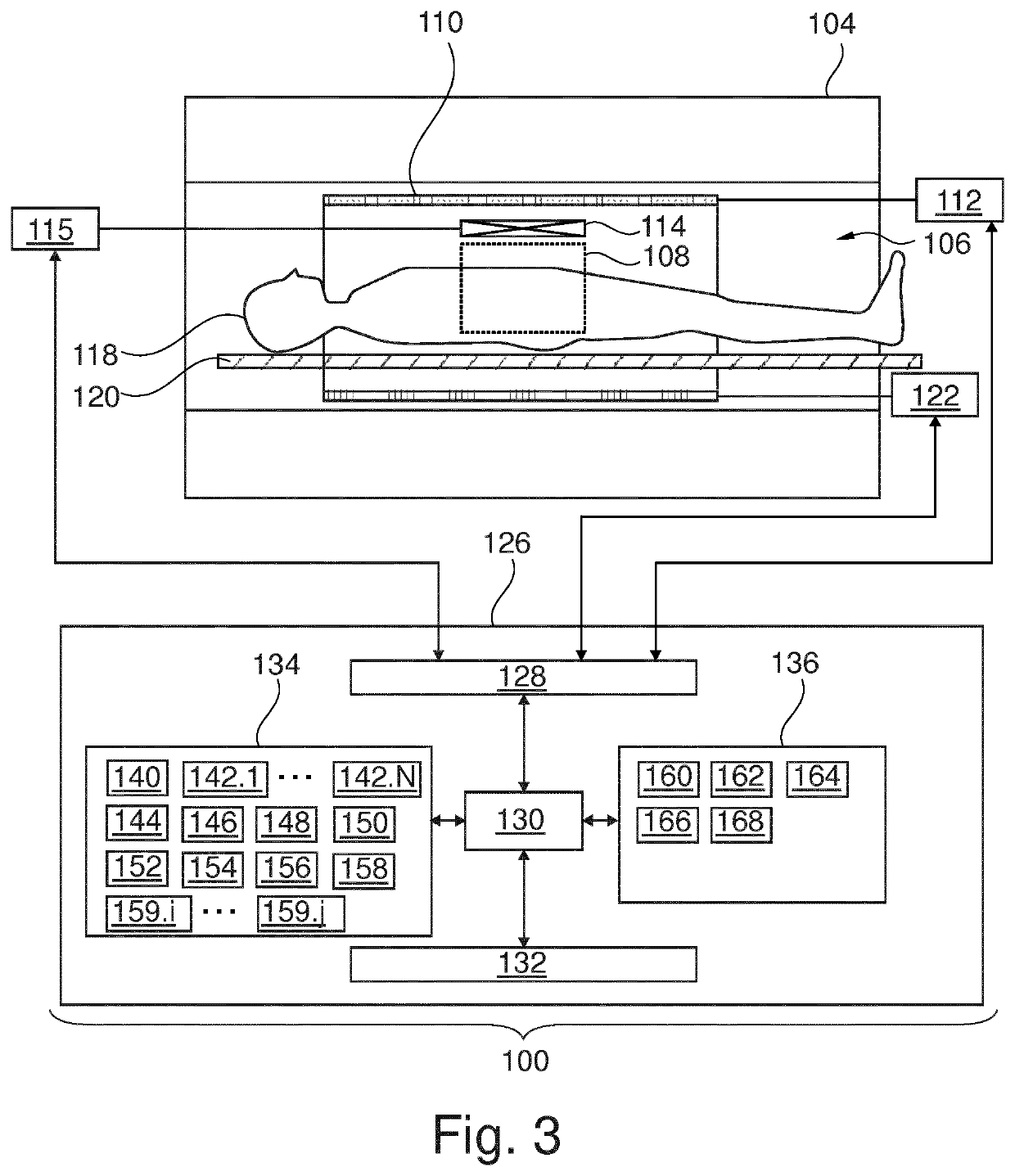
"d_n">[0144]Like numbered elements in these figures are either equivalent elements or perform the same function. Elements which have been discussed previously will not necessarily be discussed in later figures if the function is equivalent.

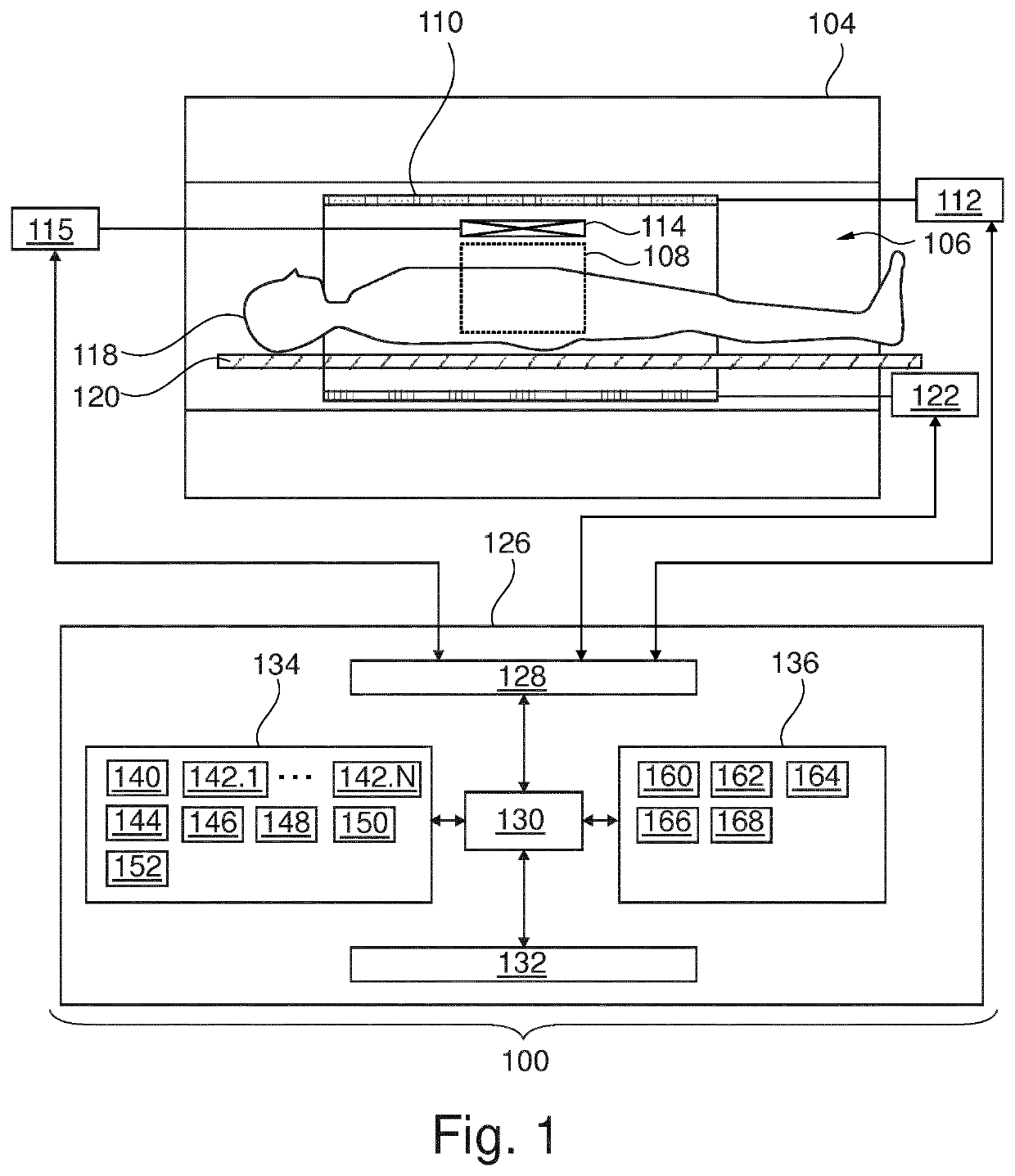
[0145]FIG. 1 shows an example of a magnetic resonance imaging system 100 with a magnet 104. The main magnet 104 is a superconducting cylindrical type magnet 104 with a bore 106 through it. The use of different types of magnets is also possible. For instance, it is also possible to use both a split cylindrical magnet and a so called open magnet. A split cylindrical magnet is similar to a standard cylindrical magnet, except that the cryostat has been split into two sections to allow access to the axial plane through the iso-center of the magnet, such magnets may for instance be used in conjunction with charged particle beam therapy. An open magnet has two magnet sections, one above the other with a space in-between that is large enough to receive a ...


PUM


Abstract

The invention relates to a magnetic resonance imaging system, the magnetic resonance imaging system (100) comprising: —a memory (134, 136) storing machine executable instructions (160, 162, 164), pulse sequence commands (140) and a first machine learning model (146) comprising a first deep learning network (502), wherein the pulse sequence commands (140) are configured for controlling the magnetic resonance imaging system (100) to acquire a set of magnetic resonance imaging data, wherein the first machine learning model (146) comprises a first input and a first output, —a processor, wherein an execution of the machine executable instructions (160, 162, 164) causes the processor (130) to control the magnetic resonance imaging system (100) to repeatedly perform an acquisition and analysis process comprising: —acquiring a dataset (142.1, . . . , 142.N) comprising a subset of the set of magnetic resonance imaging data from an imaging zone (108) of the magnetic resonance imaging system (100) according to the pulse sequence commands (140), —providing the dataset (142.1, . . . , 142.N) to the first input of the first machine learning model (146), I-n response of the providing, receiving a prediction (148, 502) of a motion artifact level of the acquired magnetic resonance imaging data from the first output of the first machine learning model (146), the motion artifact level characterizing a number and / or extent of motion artifacts present in the acquired magnetic resonance imaging data.20

Description

FIELD OF THE INVENTION[0001]The invention relates to processing motion artifacts in magnetic resonance imaging data, in particular it relates to predicting motion artifacts during magnetic resonance imaging data acquisition.BACKGROUND OF THE INVENTION[0002]Due to typically long data acquisition times of magnetic resonance imaging (MRI) procedures, motion artifacts caused by patient motion are one of the most frequent causes of image degradation of magnetic resonance images in clinical applications of MRI. Possible problems associated with motion artifacts may for example comprise that the respective magnetic resonance images may be of little or even no use for medical diagnosis due to the image degradation. Such a degraded magnetic resonance image may require a complete repetition of the magnetic resonance imaging procedure.SUMMARY OF THE INVENTION[0003]The invention provides for a magnetic resonance imaging data processing system, a method of operating the magnetic resonance imagin...

Claims


Application Information

Patent Timeline
Patent Type & Authority Applications(United States)
IPC IPC(8): A61B5/055A61B5/00G16H30/40
CPCA61B5/055G16H30/40A61B5/7267A61B5/7207G06T2207/10076G06T2207/20084G06T2207/20201G06T2207/30004G16H40/63G16H50/70G16H30/20G16H50/50A61B2576/026G06T5/73G06T5/60
Inventor SAALBACH, AXELWEISS, STEFFENSOMMER, KARSTENSCHUELKE, CHRISTOPHEHELLE, MICHAEL
Owner KONINKLJIJKE PHILIPS NV
Learn More