Apparatus and Device for the Electrical Interconnect of Implantable Devices

a technology of implantable devices and electrical interconnections, which is applied in the direction of electrical apparatus, coupling device connection, therapy, etc., can solve the problems of increasing the space required and increasing the size of the ipg devi

Pending Publication Date: 2021-06-24
DAGLOW TERRY
View PDF9 Cites 0 Cited by
  • Summary
  • Abstract
  • Description
  • Claims
  • Application Information

AI Technical Summary

Benefits of technology

[0012]As disclosed within the present specification and accompanying drawings, the lattice structure (connector housing), which is in the form of a rectangular frame or skeleton for the inclusion and support of parallel, axially co-planar spring coils, may be constructed of a metallic, semi-metallic or non-metallic material which is particularly amendable to a 3D printing process (e.g. Binder Jetting or Laser Sintering), casting, extrusion, injection molding or a similar (or combination of similar) processes whereby a single, uni-body coil spring frame is generated. Yet, where, as here, precision is an absolute requirement, 3-D printing provides the greatest degree of requisite reproducible accuracy.
[0013]Indeed, 3D printing (i.e. additive manufacturing) processes and similar processes are particularly well suited to the present invention in that these processes can create physical features that otherwise cannot be easily created with conventional machining processes or metal injection molding. Equally, by simplifying the design and construction of the present frame and lattice structure to a unibody design, as opposed to a multi-component and encapsulating housing, the present design finds itself particularly amendable to 3D printing processes to accomplish desired compactness and, most vital, appropriate connector's exacting precision and requisite density.
[0016]The frame itself exhibits protrusions above and below the centrally deposed hollow core of said frame whereas each protrusion acts as (1) a semi-circular, convex receiving guide for the concave, tubular inserted lead and (2) as a support to separate each coil spring. On either side of each protrusion lay either depressions, posts or a combination thereof (depressions with inserted posts) with which to hold and secure each coil spring and to support said coils at rest and during radial outward movement (upon lead insertion). In one embodiment said depressions themselves are sufficient to hold and secure said coil springs wherein the coil springs diameter is less than the thickness of the securing frame (i.e. in the thicker framed invention). In another embodiment, said posts are supported laterally on each end wherein the coil spring is “sandwiched” between a centrally deposed protrusion and an outwardly deposed shelf wherein said coil springs diameters may be less than, equal to or more than the thickness of the frame (e.g. in a thinner framed invention). Additionally, if each coil spring were bifurcated longitudinally at is midpoint, each coil spring may be seen to be provided open space both within the centrally deposed hollow core of the frame, for acceptance of lead insertion, and on corresponding, opposite right and left sides of each coil spring (away from the hollow center) for spring coil expansion (radially) thus providing outward relief required from lead insertion where said housing will provide physical clearance for the side loading deformation and outward V-shape (i.e. visually a “<” and “>” shape).
[0024]Too, the device itself contains novel features wherein the aforementioned connector width and resulting ability to provide an increased number of connections translates into the potential for multiple lead connectors per device which may be stacked (with an upper and lower lead insertion points as shown in FIGS. 1-3), conglomerated and / or located in various conformations and configurations all in one device. And, whereas depicted herein, stacking manifestly doubles the capacity of a pulse generating or monitoring device, this is merely representative and is not intended to limit the number and position of connectors—which could be exponentially arranged and rearranged—given the current potential for connector expansion, the number of connectors a device may support, the decreased space required, increased capacity for modular expansion as well as resultant decreases in device size requirements.
[0025]In terms of the functional components of the generating and monitoring device, the present invention exhibits additional key features aiding in its operation including, set screw securing blocks and seals. The former set screws securing blocks and screws work to secure inserted leads providing a mechanism for reversibly securing inserted leads into said device. The later insulating seals provide two proportionately advantageous elements to the present device wherein said seals allow for (a) proper connector placement and securing and (b) an insular barrier between connectors which serve to ensure the discrete conveyance or reception of signals without fear of interference from an adjacent connector.

Problems solved by technology

The current welded “canted coil” technology can only provide a minimum of 0.100″ (2.5 mm) center to center interconnect spacing which proves a space utilization defining and limiting aspect wherein limiting space for lead connectors (a) limits the number of connections (and ultimately electrodes) and (b) increases the space required for each additional electrode (thereby increasing the IPG device size).

Method used


Image

  • Apparatus and Device for the Electrical Interconnect of Implantable Devices
  • Apparatus and Device for the Electrical Interconnect of Implantable Devices
  • Apparatus and Device for the Electrical Interconnect of Implantable Devices

Examples


Embodiment Construction

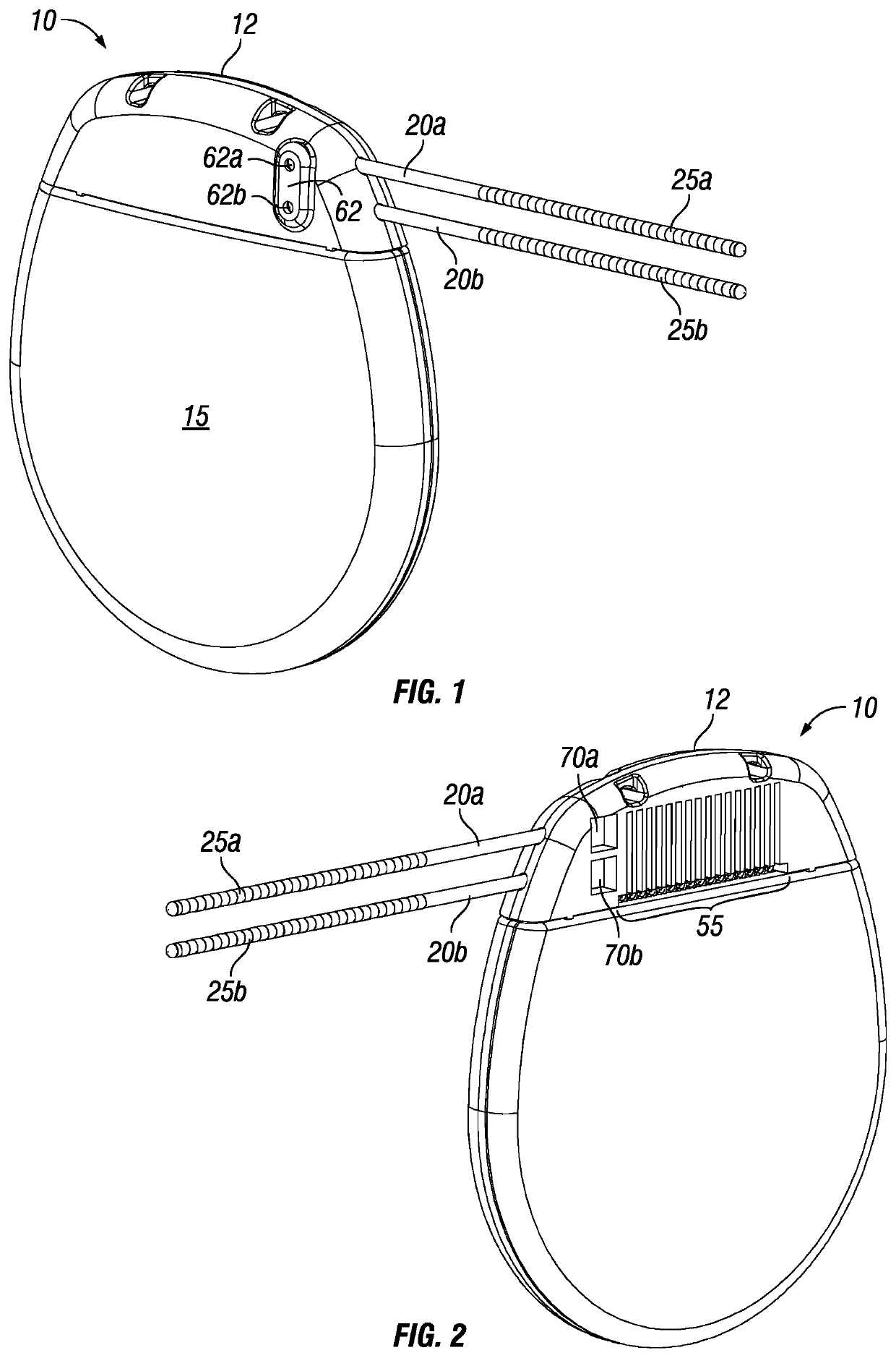
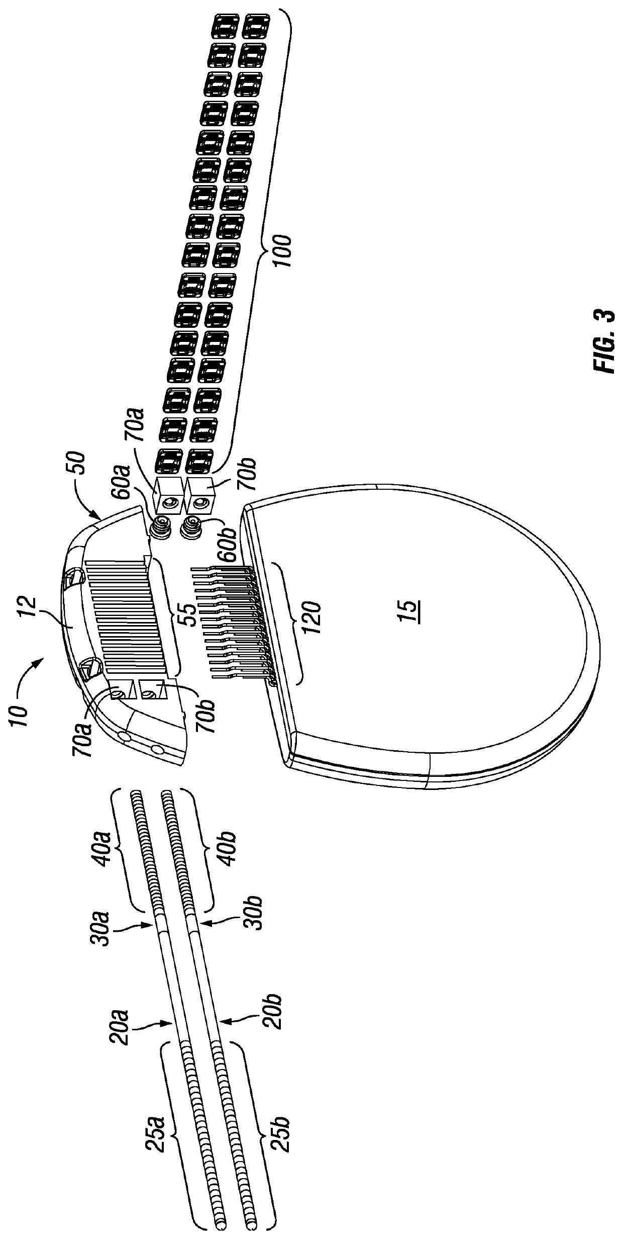
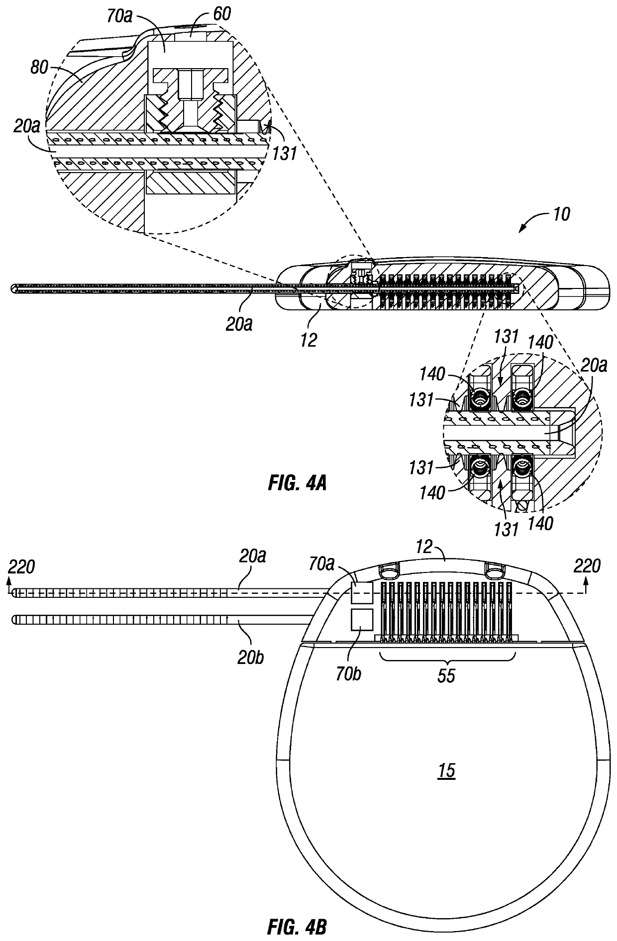
"d_n">[0040]Illustrative embodiments of preferred embodiment are described below and depicted in the figures. It must be appreciated that in the development of any preferred embodiments, numerous references are made to the spatial relationships between various components and to the spatial orientation of various aspects of components as the devices depicted in the appended drawings. However, as will be recognized by those skilled in the art after a complete reading of the present application, the devices, members, and apparatuses described herein may be positioned in any desired orientation which addresses the above deficiencies of the prior art. Thus, the use of terms to describe a spatial relationship between various components or to describe the spatial orientation of aspects of such components (e.g. lead connectors, lead electrodes, impulse generating devices, coil springs and the like) should be understood to describe a relative relationship between the components or a spatial ...


PUM


Abstract

A device and means of electrical interconnection and electrical circuit isolation between an implantable stimulation, receiving and / or data transmission lead and a pulse generating or monitoring device. Pulse generating and monitoring devices require an electrical and mechanical interconnection between the stimulation, recording and / or data transmission wires and the active electronic system, each channel or circuit electrically isolated with a high impendence barrier. This device will allow for a rectangular, high-density, unibody, secured, low insertion force connector configuration, increasing the number of connectors and reducing implant size while increasing the number of stimulation and recording channels.

Description

CROSS-REFERENCE TO RELATED APPLICATIONS[0001]This Nonprovisional Application claims priority to U.S. Provisional Patent Application No. 62 / 952,425 filed Dec. 22, 2019.FIELD OF THE INVENTION[0002]The present invention includes an apparatus, method and system of use that is directed to a low insertion force, securedly fixed and highly robust electrical and mechanical connection for an implantable medical device, generally. Said invention offers a rectangular, individualized coil-spring support structure exhibiting a high density, electrically isolated connection configuration capable of supplying and receiving electrical impulses via discrete lead electrodes providing a compact, modular construction.BACKGROUND[0003]Implantable electronic stimulation generators or implantable impulse generators (IPGs) consist of a class of devices exhibiting a means to provide stimulation to certain excitable tissues in the human body. These generators may be implanted into various locations about the ...

Claims


Application Information

Patent Timeline
Patent Type & Authority Applications(United States)
IPC IPC(8): A61N1/375A61N1/372B33Y80/00
CPCA61N1/3754B33Y80/00A61N1/37252A61N1/3752H01R13/5224H01R13/187H01R2201/12
Inventor DAGLOW, TERRY
Owner DAGLOW TERRY
Why Eureka
Try Eureka