Multilayer ceramic electronic component

Active Publication Date: 2021-07-01
MURATA MFG CO LTD
View PDF8 Cites 4 Cited by
  • Summary
  • Abstract
  • Description
  • Claims
  • Application Information

AI Technical Summary

Benefits of technology

The patent describes a method for manufacturing a multilayer ceramic capacitor that results in improved moisture resistance. The method involves forming a specific type of capacitor using a specific production process. The result is a more reliable and efficient capacitor that can withstand moisture without succumbing to damage or malfunction. This patent demonstrates how this method can improve the reliability of multilayer ceramic capacitors.

Problems solved by technology

The multilayer ceramic capacitor disclosed in Japanese Patent Laid-Open No. 05-003134, however, causes the following problems.
As a result, gaps are more likely to occur in the external electrode, thereby leading to insulation deterioration caused by moisture infiltrating during plating and remaining in the gaps.

Method used


Image

  • Multilayer ceramic electronic component
  • Multilayer ceramic electronic component
  • Multilayer ceramic electronic component

Examples


first preferred embodiment

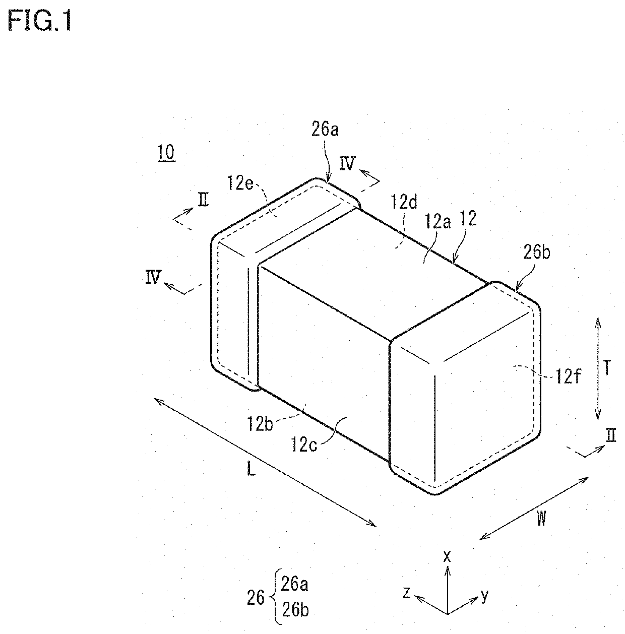
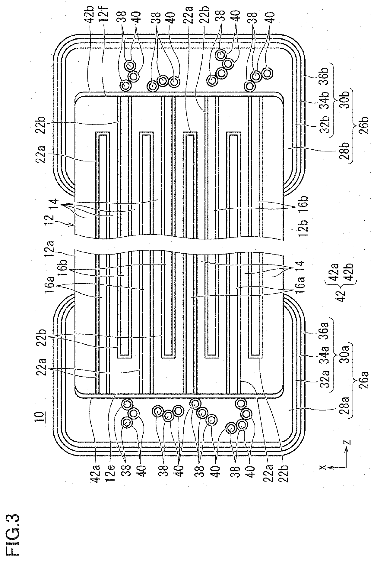
[0030]A multilayer ceramic capacitor will be described as an example of a multilayer ceramic electronic component according to a first preferred embodiment of the present invention. FIG. 1 is an external perspective view showing an example of a multilayer ceramic capacitor according to the first preferred embodiment of the present invention. FIG. 2 is a cross-sectional view taken along a line II-II in FIG. 1. FIG. 3 is a schematic cross-sectional view of external electrodes located on both end surfaces in FIG. 2 and regions therearound in an enlarged manner. FIG. 4 is a cross-sectional view taken along a line IV-IV in FIG. 1. FIG. 5 is a cross-sectional view taken along a line V-V in FIG. 2. FIG. 6 is a cross-sectional view taken along a line VI-VI in FIG. 2.

[0031]As shown in FIGS. 1 to 4, a multilayer ceramic capacitor 10 includes a multilayer body 12 having a rectangular or substantially rectangular parallelepiped shape.

[0032]Multilayer body 12 includes a plurality of stacked cera...

second preferred embodiment

[0111]In the following, a multilayer ceramic capacitor will be described as an example of a multilayer ceramic electronic component according to a second preferred embodiment of the present invention. The multilayer ceramic capacitor according to the present second preferred embodiment is a three-terminal multilayer ceramic capacitor.

[0112]Referring to FIG. 8, a multilayer ceramic capacitor (a three-terminal multilayer ceramic capacitor) will be described as an example of the multilayer ceramic electronic component according to the second preferred embodiment of the present invention. FIG. 8 is an external perspective view showing an example of a multilayer ceramic capacitor (a three-terminal multilayer ceramic capacitor) according to the second preferred embodiment of the present invention. FIG. 9 is a top view showing an example of the multilayer ceramic capacitor (a three-terminal multilayer ceramic capacitor) according to the second preferred embodiment of the present invention....

experiment examples

3. Experiment Examples

[0181]Then, a multilayer ceramic capacitor was manufactured to conduct a moisture resistance reliability test in order to check the advantageous effects of the above-described multilayer ceramic capacitor according to the present invention.

(1) Specifications of Samples in Examples

[0182]First, according to the above-described method of manufacturing a multilayer ceramic capacitor, multilayer ceramic capacitors according to Examples under the following specifications were produced.


PUM

PropertyMeasurementUnit
Lengthaaaaaaaaaa
Lengthaaaaaaaaaa
Lengthaaaaaaaaaa

Abstract

A multilayer ceramic electronic component includes a multilayer body and an external electrode on each of both end surfaces of the multilayer body. The external electrode includes an underlying electrode layer and a plating layer that is disposed on the underlying electrode layer. The underlying electrode layer includes Ni as a first metal component, Sn as a second metal component, and a ceramic material, and includes an alloy portion that is provided around the ceramic material and includes an alloyed Ni defining the first metal component and an alloyed Sn defining the second metal component.

Description

CROSS REFERENCE TO RELATED APPLICATIONS[0001]This application claims the benefit of priority to Japanese Patent Application No. 2019-233671 filed on Dec. 25, 2019. The entire contents of this application are hereby incorporated herein by reference.BACKGROUND OF THE INVENTION1. Field of the Invention[0002]The present invention relates to a multilayer ceramic electronic component.2. Description of the Related Art[0003]In recent years, multilayer ceramic electronic components represented by multilayer ceramic capacitors have been increasingly used in more severe environments than conventional environments.[0004]In order to deal with the moisture resistance load caused by infiltration of moisture from an external electrode portion under such a circumstance, a multilayer ceramic capacitor as described below has been proposed.[0005]Specifically, the proposed multilayer ceramic capacitor prevents formation of gaps between a ceramic body and an external electrode to thereby improve the adhe...

Claims


Application Information

Patent Timeline
IPC IPC(8): H01G4/248H01G4/232H01G4/30H01G4/008H01G4/12
CPCH01G4/248H01G4/232H01G4/1227H01G4/008H01G4/30H01G4/012
Inventor KANZAKI, TAISUKEONISHI, KOSUKEDOI, AKITAKA
Owner MURATA MFG CO LTD
Why Eureka
Try Eureka