Nondestructive method for measuring active area of active material
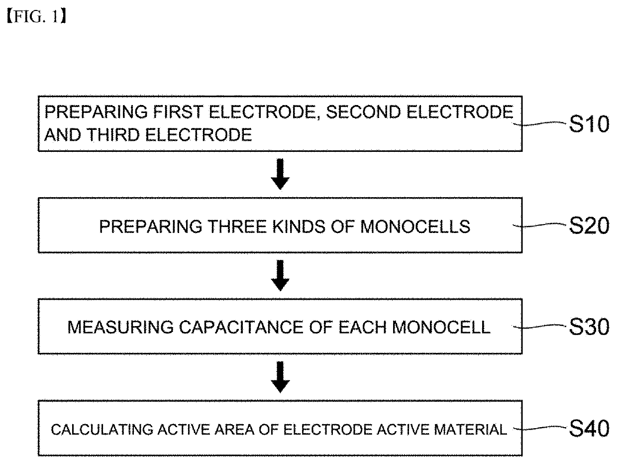
a technology of active materials and active areas, applied in the direction of sustainable manufacturing/processing, instruments, cell components, etc., can solve the problems of increasing resistance and reducing capacity, and the method requires a lot of time and effort for measurement, so as to reduce the time required for measurement and accurate active area measurement
- Summary
- Abstract
- Description
- Claims
- Application Information
AI Technical Summary
Benefits of technology
Problems solved by technology
Method used
Image
Examples
example
Preparation Example 1
[0121]Preparation of First Electrode
[0122]A copper foil having a width of 1000 mm and a thickness of 10 μm was used as the electrode current collector. 97.9 wt % LiNi0.815Co0.15Al0.035O2 as positive electrode active material, 0.5 wt % carbon nanotube (CNT) as conductive material, 1.5 wt % polyvinylidene fluoride (PVDF) as binder and 0.1 wt % PVDF as dispersant were added to N-methyl-2 pyrrolidone (NMP) which is a solvent, to thereby prepare a positive electrode mixture slurry. Thereafter, the slurry was coated on the current collector with a loading amount of 3.2 mAh / cm2, and was dried to prepare an electrode. Thereafter, the electrode was roll-pressed.
[0123]Preparation of Second Electrode
[0124]An electrode was prepared in the same manner as the first electrode except that 99.5% by weight of the positive electrode active material LiNi0.815Co0.15Al0.035O2 as the electrode mixture were mixed with 0.5% by weight of PVDF as a binder and the mixture was then coated w...
preparation example 2
[0133]Electrodes and monocells were prepared in the same manner as in Preparation Example 1, except that the conductive material dispersion conditions of the respective electrodes were different. At this time, in order to change the conductive material dispersion conditions, the conductive material dispersion was carried out three times as compared to the preparation example 1 subjected to only one step of the conductive material dispersion.
experimental example 1
[0134]Capacitance Measurement of Each Electrode
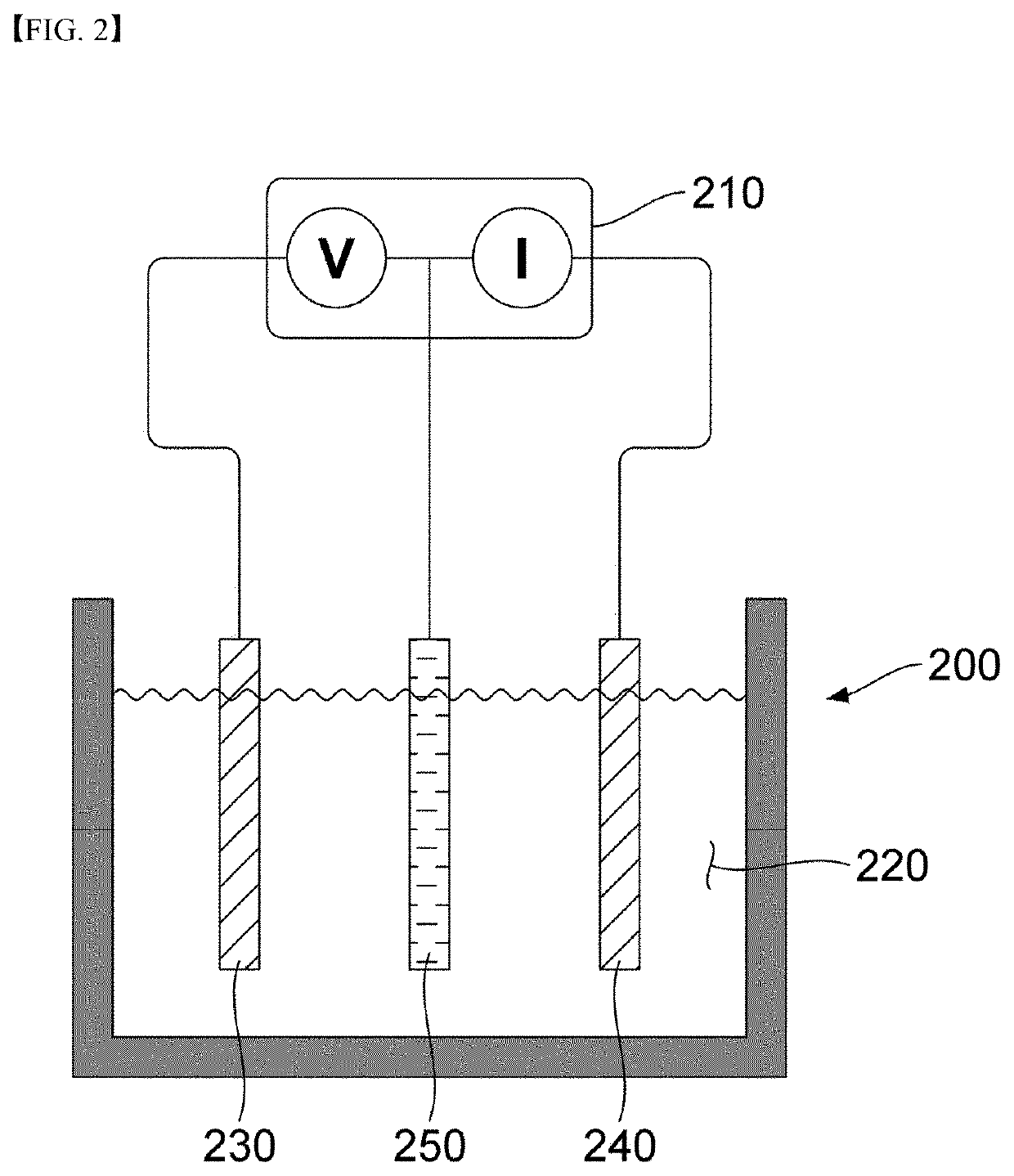
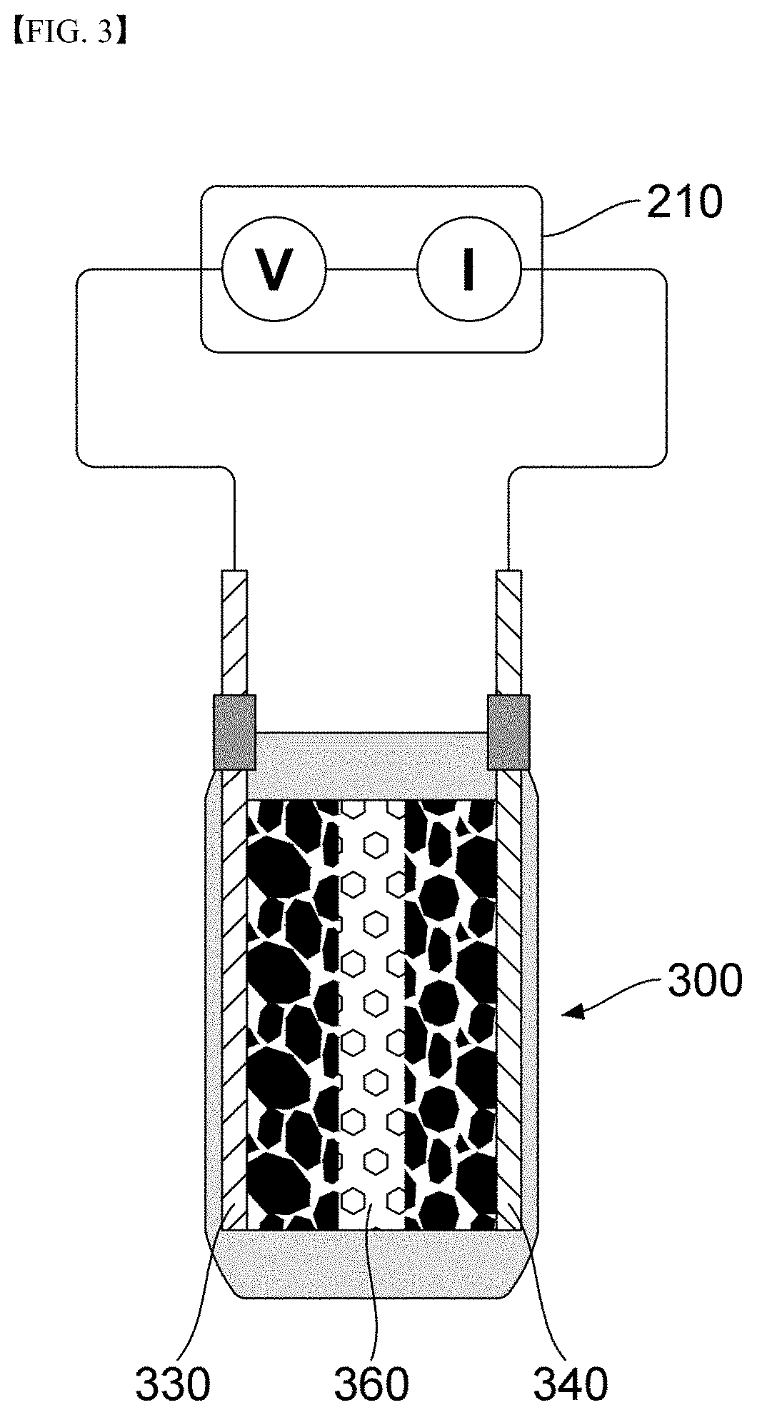
[0135]The measuring device was connected to the monocell and voltage was applied at various scan rates. The voltage was applied at scan rates of 5 mV / s, 10 mV / s, 15 mV / s, and 20 mV / s, and the voltage of the positive electrode was ramped from 0.1V to −0.1V and then returned to 0.1V.
[0136]As described above, the magnitude of the response current was recorded while applying a voltage at a constant scan rate to illustrate a cyclic voltammogram. The cyclic voltammograms of the monocell using the first electrode, the second electrode, or the third electrode in Preparation Example 1 are shown in FIG. 6. (a) is a cyclic voltammogram of a monocell using a first electrode, (b) is a cyclic voltammogram of a monocell using a second electrode, and (c) is a cyclic voltammogram of a monocell using a third electrode.) In a similar manner, the cyclic voltammogram of the monocell in Preparation Example 2 is shown in FIG. 8.
[0137]After obtaining the cycli...
PUM
| Property | Measurement | Unit |
|---|---|---|
| active area | aaaaa | aaaaa |
| conductive | aaaaa | aaaaa |
| capacitance | aaaaa | aaaaa |
Abstract
Description
Claims
Application Information
 - R&D
- Intellectual Property
- Life Sciences
- Materials
- Tech Scout
- Unparalleled Data Quality
- Higher Quality Content
- 60% Fewer Hallucinations
Browse by: Latest US Patents, China's latest patents, Technical Efficacy Thesaurus, Application Domain, Technology Topic, Popular Technical Reports.
© 2025 PatSnap. All rights reserved.Legal|Privacy policy|Modern Slavery Act Transparency Statement|Sitemap|About US| Contact US: help@patsnap.com


