Fiber-optic sensor, data glove and method for detecting curvature

a fiber-optic sensor and data glove technology, applied in the field of fiber-optic sensors for detecting curvature, can solve the problems of reducing operational reliability, enlarge the installation space required for the readout device, and complex spectrometers are required to evaluate the wavelength of reflected light, so as to achieve a wider measurement range and greater absolute stretchability

Pending Publication Date: 2021-07-08
FRAUNHOFER GESELLSCHAFT ZUR FOERDERUNG DER ANGEWANDTEN FORSCHUNG EV
View PDF0 Cites 0 Cited by
  • Summary
  • Abstract
  • Description
  • Claims
  • Application Information

AI Technical Summary

Benefits of technology

[0022]In some embodiments of the invention, the optical fiber can be a multimode fiber. This facilitates the realization of a plurality of measurement locations along the longitudinal extension of the optical fiber, wherein individual measurement locations of the curvature can be distinguished on the basis of the wavelength. In other embodiments of the invention, the optical fiber can be a single-mode fiber.
[0023]In some embodiments of the invention, the optical fiber can be a polymer fiber. Compared to a glass fiber, such a polymer fiber has the advantage that it has greater absolute stretchability. In some embodiments of the invention, the stretchability can be greater than about 5% or greater than about 10% or greater than about 15%. This can be used to realize a wider measurement range than can be achieved with other waveguides, e.g. glass fibers.
[0024]In some embodiments of the invention, the optical fiber can have a bifurcation. This allows the receiver and the light source to be arranged at the same end of the optical fiber, so that the entire signal generation and processing can be set up in a space-saving manner, for example together with the evaluation and control electronics on a single circuit carrier.

Problems solved by technology

However, this known device has the disadvantage that complex spectrometers are required to evaluate the wavelength of reflected light.
These spectrometers enlarge the installation space required for the readout device and reduce the operational reliability.

Method used


Image

  • Fiber-optic sensor, data glove and method for detecting curvature
  • Fiber-optic sensor, data glove and method for detecting curvature
  • Fiber-optic sensor, data glove and method for detecting curvature

Examples


first embodiment

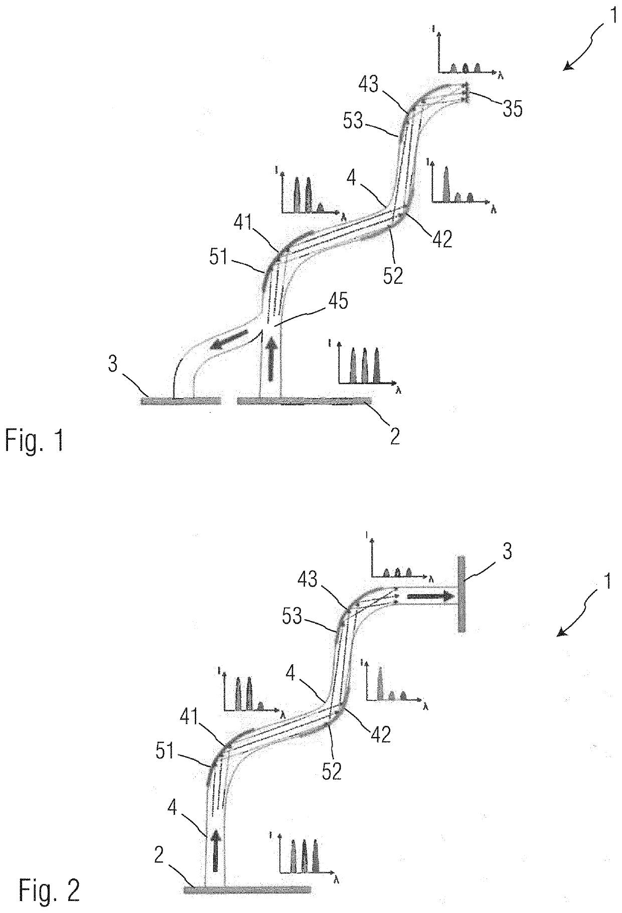
[0034]FIG. 1 illustrates a fiber-optic sensor according to the invention. The fiber-optic sensor 1 has at least one light source 2, an optical fiber 4 and a receiver 3. At least one longitudinal portion 41, 42, 43 of the optical fiber 4 is provided with a partial coating 51, 52, 53, which reduces the refractive index for light of a predetermined wavelength with respect to the remaining longitudinal portions of the optical fiber 4. In the illustrated exemplary embodiment, three longitudinal portions 41, 42 and 43 are shown, which are each provided with a different partial coating 51, 52 and 53, which reduces the refractive index for light of different wavelengths in each case and leaves light of other wavelengths essentially unaffected.

[0035]In order to explain the function of the invention, the three predetermined wavelengths are designated by the verbal designations “red”, “green” and “blue”. However, this does not mean that in all embodiments of the invention the predetermined wav...

second embodiment

[0044]With reference to FIG. 2, the invention is explained in more detail. Identical components of the invention are marked with the same reference sign, so that the following description is limited to the essential differences.

[0045]As is shown from FIG. 2, the light source 2 and the receiver 3 are arranged at different ends of the optical fiber 4. The bifurcation 45 can be omitted in this embodiment of the invention. Light of a predetermined or known wavelength distribution is coupled in by the light source 2 at the first end of the optical fiber 4. Depending on the curvature in the first, second and third longitudinal portions 41, 42 and 43, individual wavelengths and / or wavelength ranges are attenuated and the resulting intensity distribution is detected in the receiver 3. The light from the light source 2 thus reaches the receiver 3 after a single pass through the optical fiber 4.

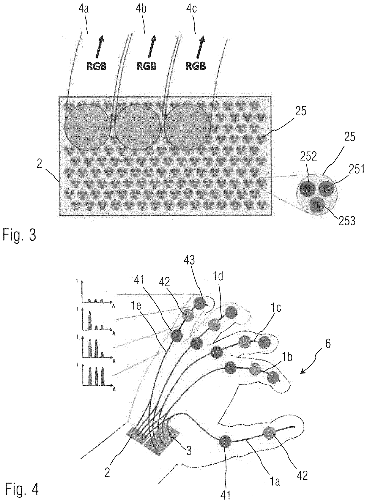
[0046]FIG. 3 again shows the coupling of the optical fiber 4 to the light source 2. A plurality of ...


PUM

PropertyMeasurementUnit
diameteraaaaaaaaaa
diameteraaaaaaaaaa
wavelength distributionaaaaaaaaaa

Abstract

A fiber-optic sensor (1) is configured to detect curvature of an article (6). The sensor includes at least one light source (2), at least one optical fiber (4) and at least one receiver (3). The optical fiber (4) has at least one longitudinal portion (41, 42, 43) in which the refractive index for light at a predetermined wavelength is reduced with respect to the remaining longitudinal portions. A method for detecting curvature of an article such as a data glove (6) or an endoscope may utilize such a fiber-optic sensor.

Description

RELATED APPLICATIONS[0001]The present application is a Bypass Continuation-in-Part of International Application No. PCT / EP2018 / 075799, filed Sep. 24, 2018 and published as WO 2020 / 064084A1. The contents of the aforementioned application are incorporated by reference in their entirety.FIELD OF THE INVENTION[0002]The invention relates to a fiber-optic sensor for detecting curvature of an article or an object. Said sensor comprises at least one light source, at least one optical fiber and at least one receiver. Furthermore, the invention relates to an article configured with such a sensor, for example a data glove or an endoscope. Finally, the invention relates to a method for detecting a curvature of an article, said method comprising the steps of coupling light from at least one light source into at least one optical fiber and evaluating transmitted light with at least one receiver.BACKGROUND[0003]A fiber-optic sensor of the type mentioned is known from US 2007 / 0297712 A1. This senso...

Claims


Application Information

Patent Timeline
Patent Type & Authority Applications(United States)
IPC IPC(8): G06F3/01G01J3/02G01B11/16
CPCG06F3/014G01B11/18G01J3/0218
Inventor ANGELMAHR, MARTINSCHADE, WOLFGANG
Owner FRAUNHOFER GESELLSCHAFT ZUR FOERDERUNG DER ANGEWANDTEN FORSCHUNG EV
Why Eureka
Try Eureka