

Polar system and delay difference calibration method
a delay difference and calibration method technology, applied in the field of polar systems, can solve problems such as signal quality decline, and achieve the effect of mitigating delay mismatch
- Summary
- Abstract
- Description
- Claims
- Application Information
AI Technical Summary
Benefits of technology
Problems solved by technology
Method used
Image

Examples
Embodiment Construction
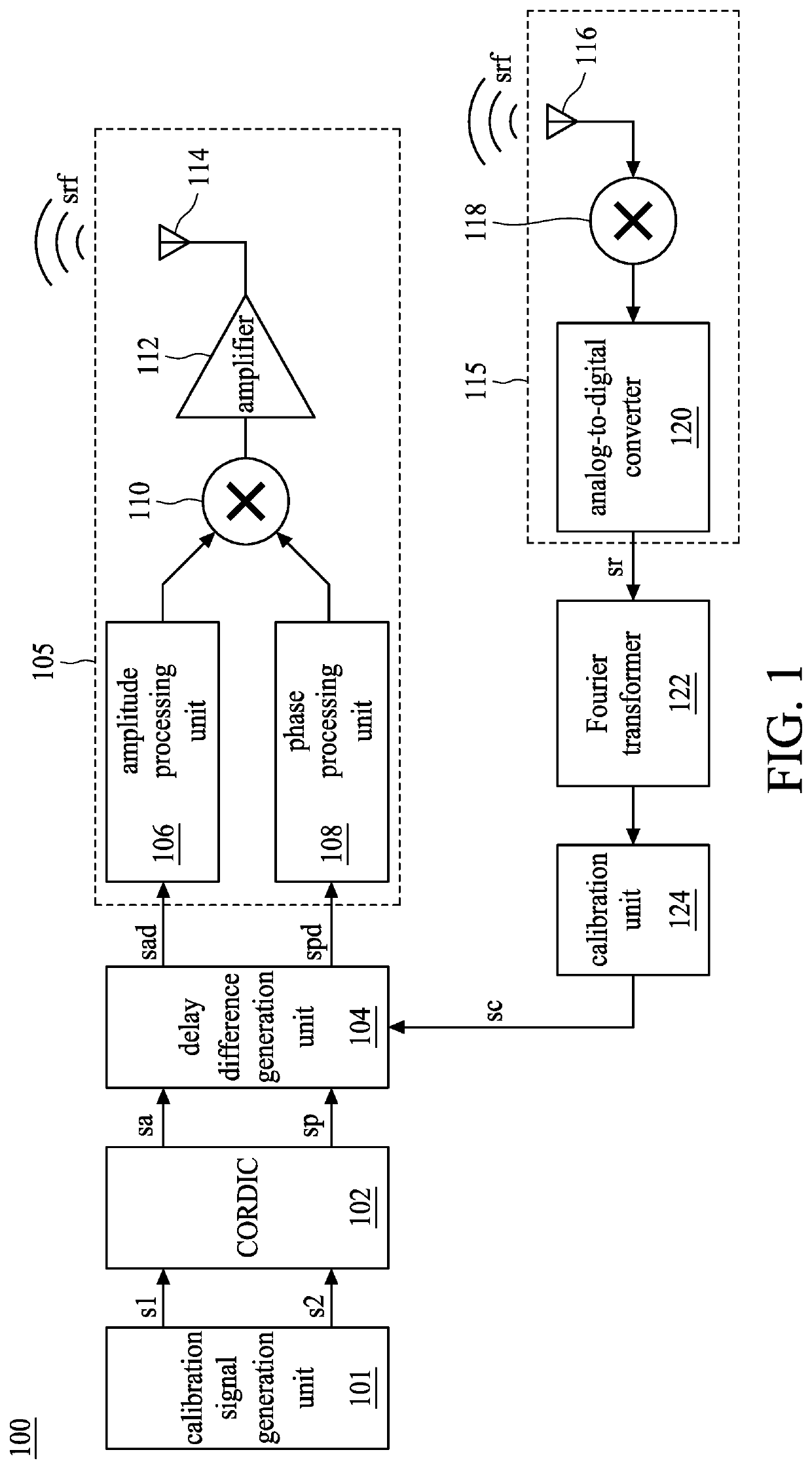
[0012]FIG. 1 is a schematic diagram of a polar system according to embodiments of the present application. The polar system 100 estimates a delay difference (i.e., a delay difference calibration value sc) between an amplitude processing unit 106 and a phase processing unit 108 under the current environment condition in a calibration mode, and the polar system 100 compensates the delay difference in a normal mode accordingly.
[0013]The calibration signal generation unit 101 is configured to generate test signals s1 and s2 to a coordinate rotation digital computer (CORDIC) 102 in the calibration mode, whereas in the normal mode, other signal generation units (not shown in the drawing) are used to generate an in-phase signal and an orthogonal signal to the CORDIC 102, wherein the in-phase signal and the orthogonal signal have the same frequency and 90-degree phase difference therebetween. The CORDIC 102 carries out the coordinate rotation digital computation according to the test signal...
PUM
 Abstract
Description
Claims
Application Information