Transmitter with delay mismatch compensation

Inactive Publication Date: 2010-12-02
ST ERICSSON SA
View PDF13 Cites 18 Cited by
  • Summary
  • Abstract
  • Description
  • Claims
  • Application Information

AI Technical Summary

Benefits of technology

[0006]It is therefore an object of the invention to provide an electronic device with a reduced delay mismatch even if the device is a mass production device.
[0009]Accordingly, a transmitter device is provided which is able to compensate for different delay mismatches in the analog part of a transmitter device by adjusting the filter values of the filter units. Therefore, such a device can be produced in a mass production as any mismatch in the analog part can be compensated accordingly.
[0011]According to a preferred aspect of the invention, the filter unit comprises a first order all pass filter with a pole and zero constellation which is tunable according to the compensation filter values stored in the table unit. Therefore, a transmitter device is provided which can compensate for delay mismatches in its analog part by selecting the pole and zero constellation of the filter units according to those values stored in the table unit, whereby a flexible transmitter device is provided.

Problems solved by technology

If a transmitter, in particular a wireless transmitter transmits a baseband signal from a digital modulator through an analog section and RF section to the antenna, impairments such as amplitude and delay mismatch may occur which in turn can lead to distortion.
A delay mismatch between the in-phase and the quadrature component of the transmit signal may result from systematic sampling-time errors in a digital-to-analog converter DAC or phase misalignment in the low pass post-filters due to process drift or design asymmetry.
Similarly, in systems with polar loop modulators a delay mismatch between amplitude and phase may be present due to a misalignment in the analog components.
However, none of these documents relate to compensation of a delay mismatch.
However, as it is usually quite difficult within a mass production to fulfill these requirements, other approaches are required.

Method used


Image

  • Transmitter with delay mismatch compensation
  • Transmitter with delay mismatch compensation
  • Transmitter with delay mismatch compensation

Examples


first embodiment

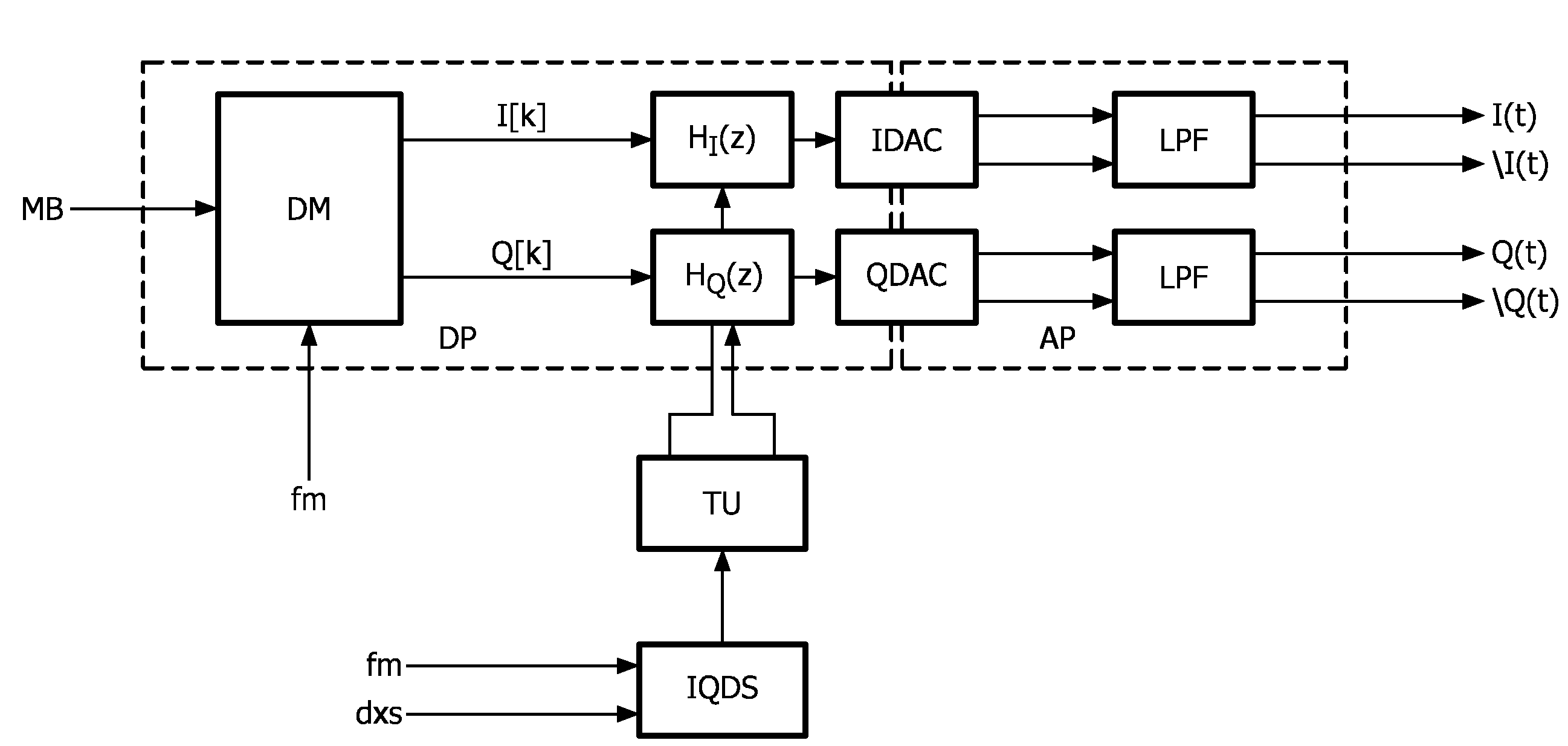
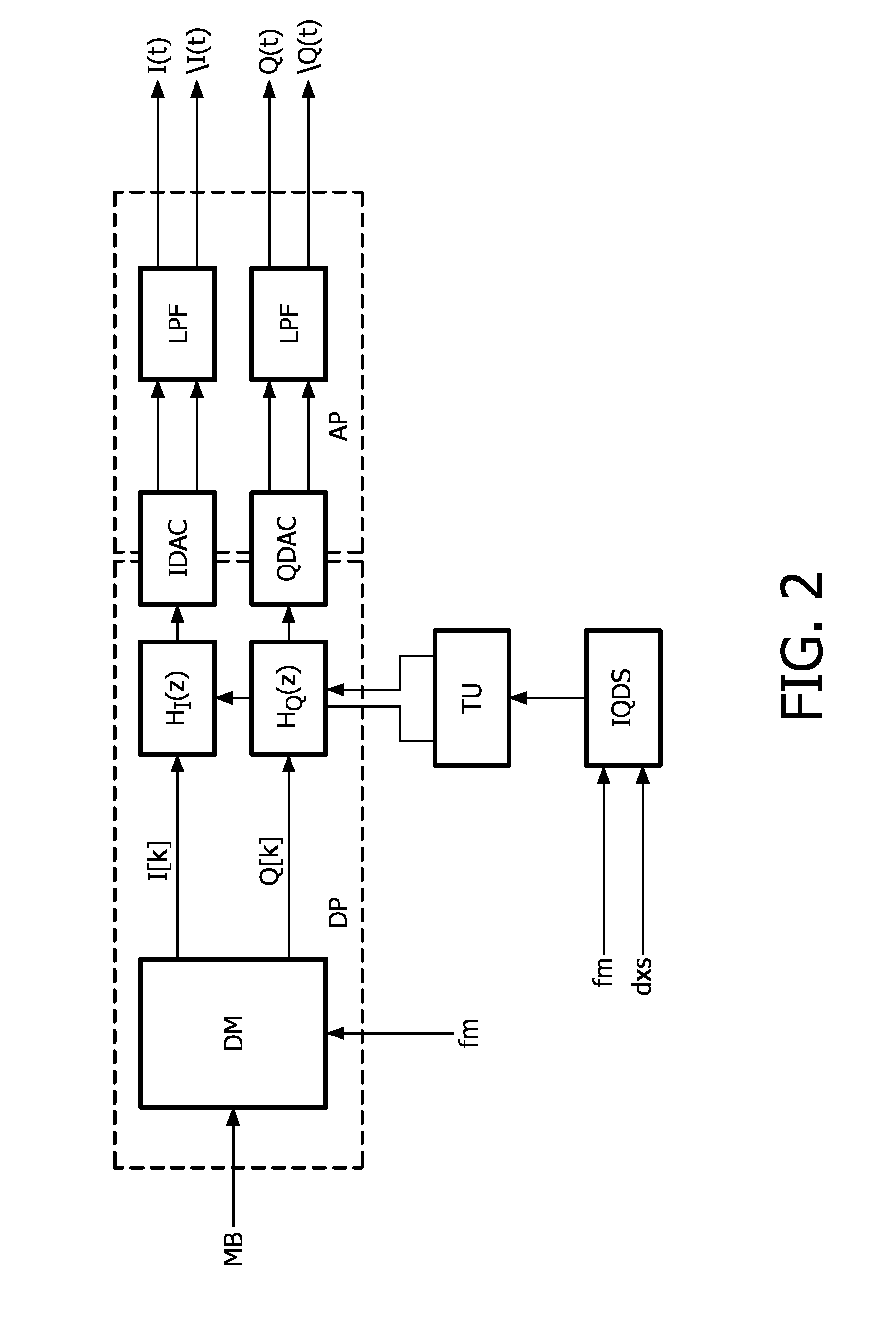
[0045]FIG. 2 shows a block diagram of a baseband transmitter according to the In addition to the elements as depicted in FIG. 1, the transmitter furthermore comprises an in-phase filter unit HI(z) which is coupled between the digital modulator DM and the in-phase digital-to-analog converter IDAC. A quadrature filter unit HQ(z) is coupled between the digital modulator DM and the quadrature digital-to-analog converter QDAC. A table unit TU is coupled to the two filter units HI, HQ while the table unit TU is in turn coupled to a I / Q delay unit IQD and a X selector unit XS. The I / Q delay unit IQD receives a master clock Fm as input and the X selector unit receives a delay X selector as input.

[0046]These filters HI, HQ are used for compensating an estimated delay mismatch into both, the I[k] and the Q[k] signal path, respectively. The filter requirements of these filters should be flat in amplitude and phase response but linearly tunable in group delay, thereby allowing to adjust for de...

second embodiment

[0059]FIG. 3 shows a block diagram of a baseband transmitter according to the The baseband transmitter comprises a digital I / Q modulator DM which receives the modulating bits MB. The in-phase and quadrature outputs I[k], Q[k] are coupled to an in-phase digital-to-analog converter IDAC and a QDAC via the filter unit HI(z) and HQ(z), respectively. The transmitter furthermore comprises a table unit TU and a I / Q delay unit IQD and a X selector unit XS. The filter units HI(z) and HQ(z) are implemented according to EQ 23. Here, the filter units are implemented in the time domain and T relates to the delay of one sampling instant. The filter coefficients rI, rQ are stored in the table unit TU which can be implemented as a RAM / ROM. By selecting a desired pole / zero constellation a delay mismatch in the analog part can be compensated.

[0060]FIG. 4 shows a block diagram of a baseband transmitter according to the third embodiment. The baseband transmitter according to the third embodiment subst...

third embodiment

[0061]The transmitter is implemented based on the integration of a first order all-pass section in order to approximate the step response of the prototype filter with a FIR section of length L depending on the chosen accuracy.

[0062]One possibility of approximating a known IIR filter by an FIR type topology of unknown length L is to minimize the squared difference of the impulse responses with coefficients ai0 . . . ain and aq0 . . . aqn, for the FIR filter in the in-phase and quadrature path, respectively, while increasing the FIR filter length L until the error criteria is fulfilled. Here, the error criteria has to be fulfilled for rε[0.5, 0.95] with step size 0.05. With a MATLAB routine it can be shown that a filter of order L=80 is needed to achieve an image rejection of IR=50.8 dB for G=1.002, and L=160 to arrive at the same performance as in the IIR case.

[0063]The advantage of choosing a FIR implementation over an IIR implementation is that neither stability nor limit cycle pr...


PUM


Abstract

A transmitter device is provided which comprises a digital part (DP) and an analog part (AP). The transmitter device furthermore comprises a digital modulator (DM) in the digital part (DP) for receiving bits (MB) and for digitally modulating the receiving bits (MB). A first (IDAC; RDAC) and second digital-to-analog converter (QDAC; ODAC) are provided. The transmitter device furthermore comprises at least one filter unit (H1; HQ; H1) which is arranged in the digital part (DP) and which is coupled between the first and / or second digital-to-analog converter (IDAC; QDAC) and the digital modulator (DM). A table unit (TU) is coupled to the at least one filter unit (H1; HQ) and is used to store pre-defined compensation filter values for the at least one filter unit (H1; HQ) which are required to compensate different delay mismatches in the analog part (AP) of the transmitter device. The filter values of the at least one filter unit (H1; HQ) are set to those compensation filter values as stored in the table unit (TU) which correspond to a determined delay mismatch.

Description

FIELD OF THE INVENTION[0001]The present invention relates to a transmitter device, a method for controlling a transmitter device and an electronic signaling device.BACKGROUND OF THE INVENTION[0002]If a transmitter, in particular a wireless transmitter transmits a baseband signal from a digital modulator through an analog section and RF section to the antenna, impairments such as amplitude and delay mismatch may occur which in turn can lead to distortion. A delay mismatch between the in-phase and the quadrature component of the transmit signal may result from systematic sampling-time errors in a digital-to-analog converter DAC or phase misalignment in the low pass post-filters due to process drift or design asymmetry. Similarly, in systems with polar loop modulators a delay mismatch between amplitude and phase may be present due to a misalignment in the analog components.[0003]An image rejection, which constitutes a measure of signal quality in GSM / EDGE systems, can be used to accura...

Claims


Application Information

Patent Timeline
IPC IPC(8): H03M1/06
CPCH04L25/49H04L2027/0016H04L27/367H04L27/364
Inventor HELFENSTEIN, MARKUSLAMPE, ALEXANDER
Owner ST ERICSSON SA
Why Eureka
Try Eureka