
Filtration system and method for filtering water

a technology of filtration system and filter water, which is applied in the field of filtration system, can solve the problems of partially demineralized water, and achieve the effect of high flow rate and high quality

Pending Publication Date: 2021-07-15
DUPONT SAFETY & CONSTR INC
View PDF3 Cites 0 Cited by
  • Summary
  • Abstract
  • Description
  • Claims
  • Application Information

AI Technical Summary

Benefits of technology

The invention is a filtration system that improves the efficiency of a tank's filtration. It achieves this by using filter modules with a high packing density, allowing more filter modules to be placed in the tank. The filter membrane is designed in a cylindrical shape, which increases the membrane area and allows for a larger flow rate of filtered water. Additionally, the system includes a sealing arrangement to prevent water from flowing in the axial direction outside of the filter membrane. The filtration module is fixed in the tank to prevent movement. These technical effects result in a more effective and efficient tank filtration system.

Problems solved by technology

Thus, while ultrafiltration already filters bacteria, viruses and macromolecules, leading to water with drinking quality, nanofiltration leads to partially demineralized water.

Method used

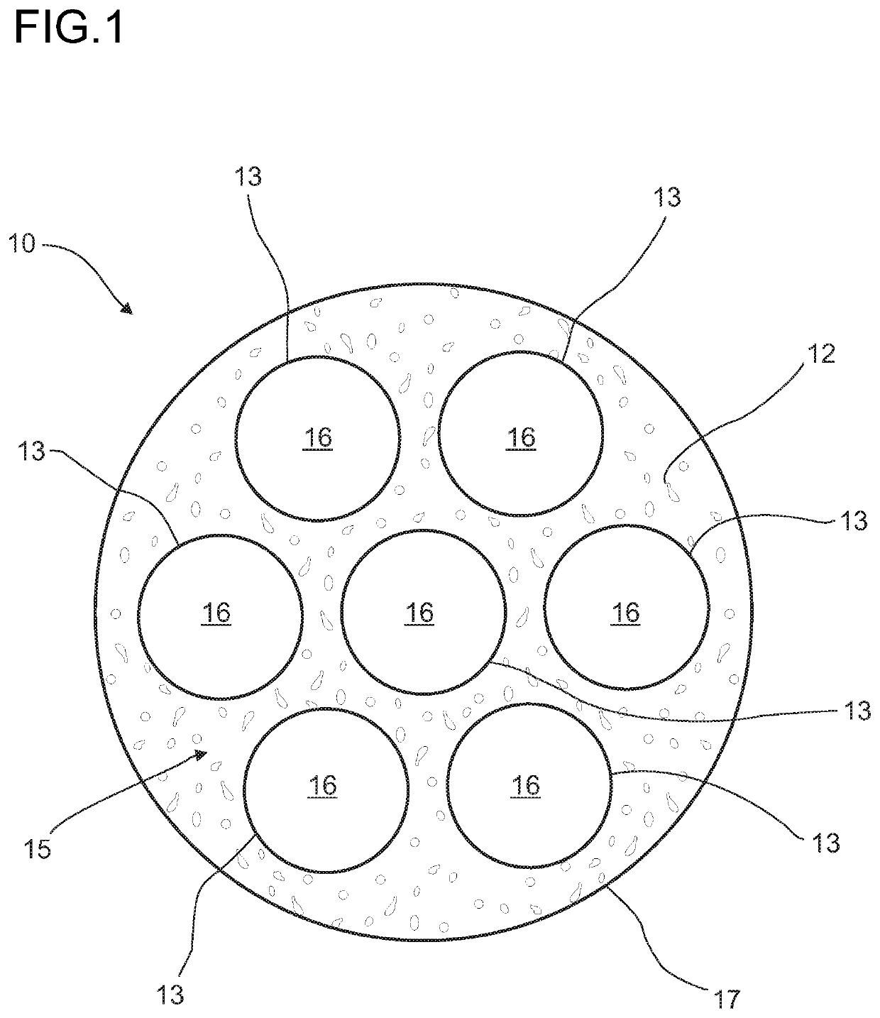

Image

  • Filtration system and method for filtering water
  • Filtration system and method for filtering water
  • Filtration system and method for filtering water

Examples


first embodiment

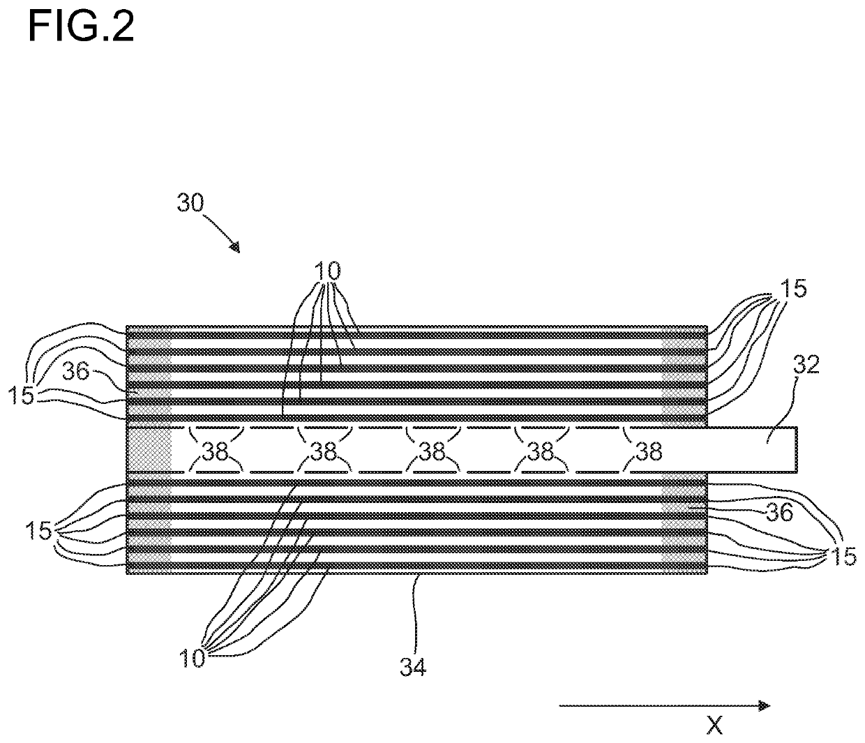
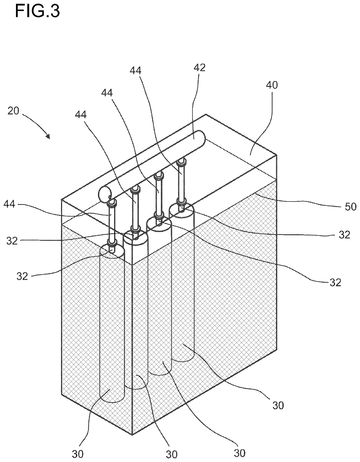
[0052]FIG. 3 shows a schematically given perspective semi-transparent view at a filtration system 20 according to a The filtration system 20 comprises a tank 40 that is filled with water to be filtered up to a water level 50. The filtration system 20 further comprises several filtration modules 30 as shown in FIG. 2. The filtration modules 30 each comprise several filter membranes 10 for filtering the water and a filtrate pipe 32 for drawing filtered water out of the tank 40.

[0053]The filtration modules 30 are arranged in the tank 40 such that the filter membranes 10 are submerged completely in the water. Hence, the filtration modules 30 are arranged in the tank 40 such that the front sides 15 of all filter membranes 10 are located below the water level 50. Thus, the front sides 15 of the filter membranes 10 are in contact with the water.

[0054]In this first embodiment, the filtration modules 30 are arranged in the tank 40 such that the axial direction x extends vertically. The filt...

second embodiment

[0057]FIG. 4 shows a schematically given perspective semi-transparent view at a filtration system 20 according to a The filtration system 20 comprises a tank 40 that is filled with water to be filtered up to a water level 50. The filtration system 20 further comprises several filtration modules 30 as shown in FIG. 2. The filtration modules 30 each comprise several filter membranes 10 for filtering the water and a filtrate pipe 32 for drawing filtered water out of the tank 40.

[0058]The filtration modules 30 are arranged in the tank 40 such that the filter membranes 10 are submerged completely in the water. The filtration modules 30 are arranged in the tank 40 such that the front sides 15 of all filter membranes 10 are located below the water level 50. Thus, the front sides 15 of the filter membranes 10 are in contact with the water.

[0059]In this second embodiment, the filtration modules 30 are arranged in the tank 40 such that the axial direction x extends vertically. The filtration...


PUM


Abstract

The invention relates to filtration system (20), comprising a tank (40) filled at least partly with water to be filtered, and at least one filtration module (30), the at least one filtration module (30) comprising at least one filter membrane (10) for filtering the water comprising a substrate (12) which is penetrated by at least one capillary (16), and at least one filtrate pipe (32) for drawing filtered water out of the tank (40), whereat the at least one filtration module (30) is arranged in the tank (40) such that the at least one filter membrane (10) is submerged at least partly in the water to be filtered. The at least one filtration module (30) is designed and arranged such that water to be filtered flows into the at least one capillary (16) and from the at least one capillary (16) through the substrate (12) into the filtrate pipe (32). The invention also relates to a method for filtering water by means of a filtration system (20) according to the invention, whereat the water to be filtered is drawn into the at least one capillary (16) and from the at least one capillary (16) through the substrate (12) into the filtrate pipe (32) and from the filtrate pipe (32) out of the tank (40).

Description

DESCRIPTIONTechnical Field[0001]The present invention relates to a filtration system, comprising a tank filled at least partly with water to be filtered, and at least one filtration module, whereat the at least one filtration module comprises at least one filter membrane for filtering the water, and at least one filtrate pipe for drawing filtered water out of the tank, whereat the at least one filtration module is arranged in the tank such that the at least one filter membrane is submerged at least partly in the water to be filtered. The present invention also relates to a method for filtering water by means of a filtration system according to the invention.Prior Art[0002]Water treatment is one of the most vital applications of filtration processes which thus experience a strong interest not only due to global water scarcity, particularly in draught-prone and environmentally polluted areas, but also due to the continuous need for drinking water supplies and for treatment of municipa...

Claims


Application Information

Patent Timeline
IPC IPC(8): B01D63/04B01D61/18C02F1/44
CPCB01D63/046B01D61/18C02F1/444B01D2313/04B01D2313/125B01D2313/20B01D2317/06B01D2313/44B01D2315/06B01D2315/08B01D2313/54B01D2317/04B01D2313/243B01D63/02B01D63/04B01D63/043B01D65/02B01D69/08B01D69/082C02F2201/003B01D2313/201B01D2313/206
Inventor HEIJNEN, MARTIN
Owner DUPONT SAFETY & CONSTR INC
Learn More